Continue to Site

Welcome to EDAboard.com

Welcome to our site! EDAboard.com is an international Electronics Discussion Forum focused on EDA software, circuits, schematics, books, theory, papers, asic, pld, 8051, DSP, Network, RF, Analog Design, PCB, Service Manuals... and a whole lot more! To participate you need to register. Registration is free. Click here to register now.

help me to design running LED with shift register for a digital roulette

Status
Not open for further replies.

antontalok

Newbie level 5
Joined
Oct 9, 2010
Messages
10
Helped
0
Reputation
0
Reaction score
0
Trophy points
1,281
Activity points
1,360
so, i want to make a running LED shaping a circle. just like arcade game which have many LEDs and they flash in turn.
i am planning to have about 65 LEDs

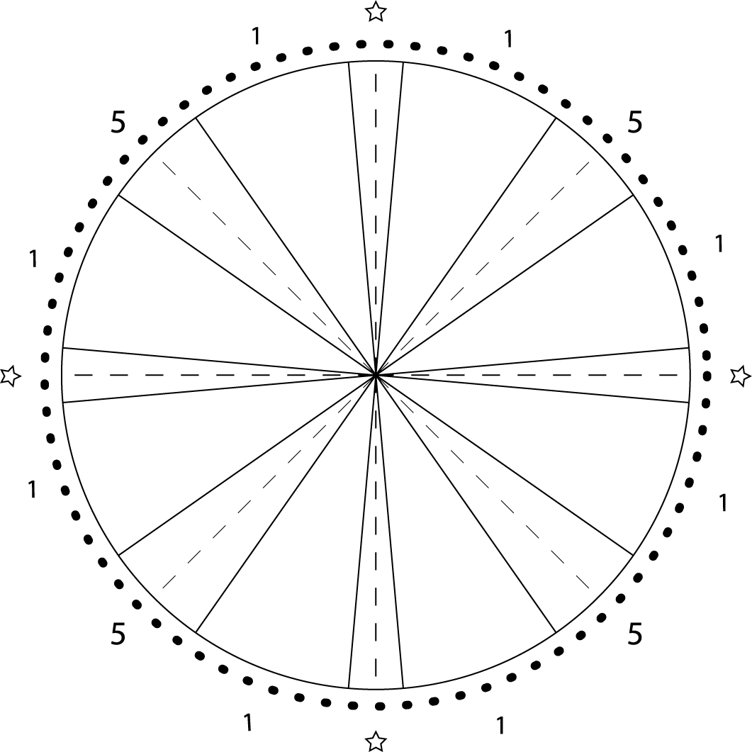
here is the picture how it's gonna look like.

i want those LEDs flash one by one.
and shape a circle
i want that done by several SIPO shift register. i think i might be using 74164.

i also have GAL as the decoder and logic gates.
when i press a button, the shift reg will start to turn on the LEDs, when i press the button again i want that LED stop at where i pressed the button.

there's point will earn to where it stop
i will have it accumulate by GAL and shown in two 7 segment.

and user is allowed to play three times only. (means three times to press the button start and stop).
the user should press Reset button provided.

and then so.

anybody could help me with this design?
\thanks
 
Last edited:

Oops. Sorry, it is a counter...but it will count really high.
 

1 - Define your game behaviour.

While thinking about what you said i can separate nine stages of your game :

1 - User press buttom.
2 - Game resets (all things go 0) : Reset.
3 - Preload shift register 1 with only first bit on (Load).
4 - Stop loading the 1st shift register.
5 - Start sending clock pulses to make the barrel roll.
6 - Wait user stop pressing the button.
7 - Stop clock from rotating the big shift register.
9 - If user presses button again, goes back to 1.

Well, i will try to build a circuit that does this in circuit maker.

2 - Second step, draw a circuit to match the behaviour (Select components or sub-circuits that does what you need).
3 - Test in a CAD tool.
4 - Simplify the circuit.
5 - Build with real world components.
6 - Enjoy.

Edit : I see that you want to accumulate the results, hmm... you have two resets them, one that resets the shift register back all leds off, and one that resets the game points.
 
Last edited:

1 - Define your game behaviour.

While thinking about what you said i can separate nine stages of your game :

1 - User press buttom.
2 - Game resets (all things go 0) : Reset.
3 - Preload shift register 1 with only first bit on (Load).
4 - Stop loading the 1st shift register.
5 - Start sending clock pulses to make the barrel roll.
6 - Wait user stop pressing the button.
7 - Stop clock from rotating the big shift register.
9 - If user presses button again, goes back to 1.

Well, i will try to build a circuit that does this in circuit maker.

2 - Second step, draw a circuit to match the behaviour (Select components or sub-circuits that does what you need).
3 - Test in a CAD tool.
4 - Simplify the circuit.
5 - Build with real world components.
6 - Enjoy.

Edit : I see that you want to accumulate the results, hmm... you have two resets them, one that resets the shift register back all leds off, and one that resets the game points.

i got what you mean.
i also already planned those stages as well as yours.

but seems that your idea comes out to be more button than mine, isn't it?
you tell me that i should have Reset for points, reset for shift register, start rotating LED, stop rotating LED, push button to load first bit into shift register.

can i simplify those button into : reset for both points and shift register, start and stop LED, and push button to load first bit. so it's gonna be only 3.

and another question is, how could GAL or any other component inside knows where the LED stop? i mean, when the LED stop at point 5, the GAL will accumulate a bit of 0101 and so on.

again, this is the most difficult for me. how to create only 3 attempts allowed for user to play? i dont think GAL could do such things. so i want to know another creative idea that could manipulate kind of this thing.

thanks a lot for any answer.
i really appreciate them.
 

Hm... you can simplify the buttons, yes, you can make a button trigger two things.

But from what you describe, a microcontroller is way more suited to the task than a GAL.

You can count the number of clock pulses using a microcontroller (the microcontroller becomes the clock source of the shift registers, each pulse = one step ahead until the end, where the count flips back to 0).

And a microcontroller can very well sum the game points, coordinate the reset sequence and pre-load etc.

I think its more suitable than a GAL. And can be quite cheap.

yes. i know that microcontroller is much better.

but this is a task. so i dont have anything i could do than to obey the rules which doesn't allow me to use any MCU.
this is a lesson about logic gate. so we are taught to learn about digital logic system using GAL.
 

I agree that a micoproc is the way to go but its just more fun doing it discreat
Try for clock--555 astable--control freg pot sub with LDR. Charge light source withR/C
and start sequence. As source of light goes down freq will change causing leds to slow down and stop.Kinda like "Wheeel of Fortune). Have you considered opening a ****** in Las Vegas.
Good Idea reminds me of Pong sorta.

---------- Post added at 22:29 ---------- Previous post was at 22:25 ----------

Your wheel looks like the old Sodar (not Sonar) fish finders.

---------- Post added at 22:39 ---------- Previous post was at 22:29 ----------

Comment--I like CAD but in the real world when it works in cad it never works inthe field. Keep it up bro
 

The circuit below uses a hex Schmitt Trigger inverter (74HC14) and two 8 bit Serial-In/Parallel-Out shift registers (74HCT164 or 74HC164) to sequence 16 LEDs. The circuit can be expanded to greater lengths by cascading additional shift registers and connecting the 8th output (pin 13) to the data input (pin 1) of the succeeding stage. A Schmitt trigger oscillator (74HC14 pin 1 and 2) produces the clock signal for the shift registers, the rate being approximately 1/RC. Two additional Schmitt Trigger stages are used to reset and load the registers when power is turned on. Timing is not critical, however the output at pin 8 of the Schmitt Trigger must remain high during the first LOW to HIGH clock transition at pin 8 of the registers, and must return low before the second rising edge to load a single bit. If the clock rate is increased, the length of the signal at pin 9 of the Schmitt Trigger should be reduced proportionally to avoid loading more than one bit. The HCT devices will normally provide about 4 mA (source or sink) from each output but can supply greater currents (possibly 25 mA) if only one output is loaded. The common 150 ohm resistor restricts the current below 25 mA using a 6 volt power source. If the circuit is operated with two or more LEDs on at the same time, resistors may be needed in series with each LED to avoid exceeding the maximum total output current for each IC of 25 mA. For greater brightness, individual buffer transistors can be used..


Hi,

For the running led you can use the daretodream25's suggestion and...

For binary counting using only logic, you can use a "D Flip-Flop" counter. This can match your needs to know witch led is lit up and how many times the player depressed the start button.

For example have a look at:
Johnson Counter

You can achieve the same goal with JK flip-flop.
 

Status
Not open for further replies.

Part and Inventory Search

Welcome to EDABoard.com

Sponsor

Back
Top