Switch_639
Member level 1
- Joined
- Dec 27, 2009
- Messages
- 34
- Helped
- 0
- Reputation
- 0
- Reaction score
- 0
- Trophy points
- 1,286
- Location
- Port Elizabeth, South-Africa
- Activity points
- 1,542
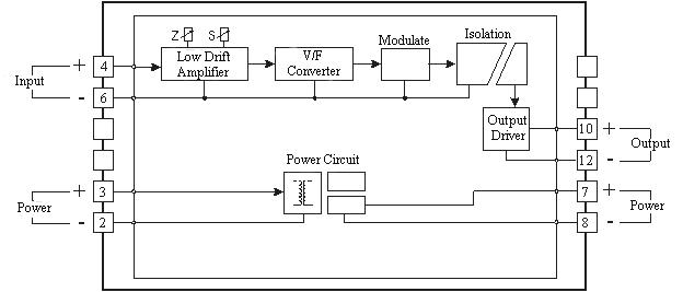
V-F Converter cct
I didn´t know where else to post, I am new here... if its wrong forum tell me... I am a student and have some questions on this circuit...
here it is...
**broken link removed**
how do I adjust the gain with the 2K rheostat and know its correct? also the optional offset adjust of the OPAMP, when is this correct? at moment I have the cct built... I am getting output at pin3 of LM331... its a small signal around +/- 1V...
any help will be appreciated... I can not get a square wave pulse on oscilloscope either, but I might be trying to read it in incorrect manner...
") & F=1/Time...
& F=1/Time...