Continue to Site

Welcome to EDAboard.com

Welcome to our site! EDAboard.com is an international Electronics Discussion Forum focused on EDA software, circuits, schematics, books, theory, papers, asic, pld, 8051, DSP, Network, RF, Analog Design, PCB, Service Manuals... and a whole lot more! To participate you need to register. Registration is free. Click here to register now.

help! Led Matrix Row Transistor

Status
Not open for further replies.
i will use 74ls138 instead of that.. 74hc154 i also output low.. so its ok to change that driver.. :)
 

So the transistors go to the output of the 74ls138, there are 7 lines driving all the leds, so you need 7 pair of transistors, why did you say 15 cathode rows (and transistors ),
I'm confused with what you are saying, can you provide a schematic that shown what you have done , not the old one.

Alex
 

i am planning to expand my rows to 14.. thats why i will use 2 74ls138 in my rows.. my question is that, what proper transistor should i use in my rows..
 

ok 14 rows, how many displays feed in parallel from each row,
and how many columns belong in each row .

For example in your previous schematic you had 7 rows going to 8 leds, each row had 8 columns so the max was 8*8=64 leds in each step of the multiplexing

Alex
 

i think 14 rows going to 8 columns.. i have a 14x40 led matrix that i made.. im not using 5x7 led modules here..
 

so the maximum current for each transistor will be 80ma since it can light only up to 8 leds in each row is that right?
So all that talk about the power supply not being enough was without point, i can't give you a solution without proper circuit description.

Alex

---------- Post added at 19:16 ---------- Previous post was at 19:07 ----------

that was my mistake , you said 40 leds not 8 so 400mA total

Alex
 

thank you sir.. but what if 40 leds in a rows.. whats the proper solution for this? i just want to deal with the worst if ever.. thank you sir..

circuit description:

in my 74HC595.. the output of my 595 has a 33ohm resistor.. and my rows at first is connected to PNP transistors which i doubt is wrong implementation..
 

i think 14 rows going to 8 columns.. i have a 14x40 led matrix that i made.. im not using 5x7 led modules here..

I'm still trying to understand what you mean by that,
do you have 5 displays 14x8 each?
so each of the 14 rows goes to 5 displays and each one has 8 columns, total of 5*8=40 leds?

Alex
 

**broken link removed**
here's my picture.. hahaha sorry it kinda messy hahaha~ ;p it is not finish yet..
 

nice picture but i don't know the connection on that...
when you give power to only 1 row how many leds can you light in all the connected displays?

Alex
 
ahmmm.. about 20 leds will turn on in a row in my led.. so i would like to ask what if 40 leds will turn on in a row?
 

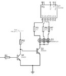
The transistor has to be selected to to be able to give that current also also the resistors have to be calculated so that the transistor will be able to give that.
for example something like this can give up to about 500ma, all the leds must have resistors in the anode side
driver.jpg

Alex
 
what is that "value" the supply voltage?

it means i will implement 2 NPN transistor in my 14 rows? how about selecting NPN transistor that is able to supply current about 500mA? so that i could minimize the use of NPN here..

---------- Post added at 19:00 ---------- Previous post was at 18:58 ----------

im kinda confused about the anode side of the LED.. because in my anode i have my 74hc595 drivers..
 

you will use 14 pairs or transistors in the rows to be able to control them individually,
each anode should have a resistance, connected between the 74HC595 and the anode of the display, the value will depend on the intended current,
12v is the power supply but in your case the schematic will look like this
driver2.jpg

if the power supply to the first transistor is 5v then use a 1k resistor instead of the 2k
The 10k input will connect to the output of each roe (74ls138)

Alex
 
Last edited:
thankz sir.. i might try this one.. ill update you about my work.. thank you sir

---------- Post added at 20:07 ---------- Previous post was at 20:02 ----------

im using raster scanning in my rows, is it ok if i implement those NPN's?
 

hehehe... because the rows are scanning.. not controlled manually by pic.. correct me if im wrong sir...
 

the rows are not scanned on their own, you use the pic to drive the 74ls138 and select which row gets the gnd,
then the leds on that enabled row than also get a positive voltage from the 74HC595 are turned on.
then you enable row 2..3..4 etc one at a time using the pic.

Alex
 
thank you for the reply sir.. i hope 2n222a is available here in our city...
 

it is 2N2222 ,not 2N222 and it is a very common transistor, you can use any transistor that has a rating for collector current above 500mA,
2N3904 can only work up to 200mA so it can't be used for the output.

Alex
 

Status
Not open for further replies.

Similar threads

Part and Inventory Search

Welcome to EDABoard.com

Sponsor

Back
Top