Welcome to our site! EDAboard.com is an international Electronics Discussion Forum focused on EDA software, circuits, schematics, books, theory, papers, asic, pld, 8051, DSP, Network, RF, Analog Design, PCB, Service Manuals... and a whole lot more! To participate you need to register. Registration is free. Click here to register now.
i want to design a mixer for optoelectronic data transmission where the input frequency is 26 GHz, LO frequency 13 GHz (or below) and output frequency 40 GHz. my first question is how can i match the input impedance (50 ohm) using transmission Lines. i know i could use the Inductive degeneration but that is not enough.
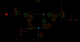
You can do any of the standard techniques followed in RF design for matching. Like, inductor emitter degeneration with Cgs and a series L should give the 50ohms impedance you want. This, as known, is the best for both noise and power matching. Else, you can have a shunt resistance at the base to get the matching. i.e the bias resistance (R9 in your schematic), as it is with the 220fF cap (C23 cap will have to be removed), can be made to be the 50ohms matching resistor. However, it adds a lot of noise putting the minimum noise figure to be more than 3dB.
300um TL is fine. But, I don't think the other two TLs are necessary to be transmission lines as they run for shorter distances. You can make them wide enough to carry the required signal current. For simulations, extract them using EMX or some such tools and make sure you are not bandwidth limited anywhere.
I am assuming the 1.5pH inductor you are using on the emitter is not by design. Rule of thumb is 1um of routing gives roughly a 1pH of inductor. So, never use inductors below say 50pH in your schematic simulations as it is going to change a lot once you make actual connections in layout.
This site uses cookies to help personalise content, tailor your experience and to keep you logged in if you register.
By continuing to use this site, you are consenting to our use of cookies.