Continue to Site

Welcome to EDAboard.com

Welcome to our site! EDAboard.com is an international Electronics Discussion Forum focused on EDA software, circuits, schematics, books, theory, papers, asic, pld, 8051, DSP, Network, RF, Analog Design, PCB, Service Manuals... and a whole lot more! To participate you need to register. Registration is free. Click here to register now.

Fluctuation in modulator's power supply in wireless transmission

Status
Not open for further replies.

88sanz

Newbie level 5
Newbie level 5
Joined
Sep 24, 2010
Messages
9
Helped
0
Reputation
0
Reaction score
0
Trophy points
1,281
Activity points
1,368
Hi,

I've designed a modulator using MX614P for my project of satellite communication (CubeSat). A COTS ALINCO DJ-S45E transceiver was used to transmit data received from the modulator.
However, when I connect the transceiver to my modulator, it would cause fluctuation in the power supply for my modulator. I would like to ask what would be the cause for this situation and how to resolve it?

Thanks in advance.
 

Are you the same person as the initiator of **broken link removed** Cubesat related topic? If yes, please give more details about your modulator (a schematic of what you did would be highly welcomed) because I have noticed you usually make many elementary mistakes.
 

That was posted by my group mate for the project, I actually work on the software part. He's not in the country at the moment. I'm currently testing the modulator and realized this issue.

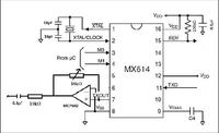
This is the only schematic I have on hand.


I would also like to ask if it's due to the current limit of the transceiver? If such, what will be the normal current limit for the transceiver as I couldn't find the information from the manual.

Thanks.
 

That schematic is wrong for reasons already explained HERE.
However, I thought that your team mate had already fixed the problem.
That triangular OA (Operational Amplifier) shouldn't be there.
 

sorry, the schematic was wrong. The Op-Amp was removed and a variable resistor was used.
 

Hi,

I've designed a modulator using MX614P for my project of satellite communication (CubeSat). A COTS ALINCO DJ-S45E transceiver was used to transmit data received from the modulator.
However, when I connect the transceiver to my modulator, it would cause fluctuation in the power supply for my modulator. I would like to ask what would be the cause for this situation and how to resolve it?
Thanks in advance.

ok now we have the background from you :) there are several possibilities for the voltage fluctuations.
1) unstable PSU for the modulator
2) Most likely ... RF getting back into the modulator
a) ... is the transmitter running on an outside antenna ? or is the antenna/ dummy load on the workbench beside the modulator board ?
b) ... is the modulator shielded i.e. in its own metal case with feedthrough capacitors bring in power and signal lines ?
c) ... do have appropriate RF decoupling on the DC line on the modulator board ?

how you answer those Q's will probably tell you where your problems lie ;)

Dave
 
  • Like
Reactions: 88sanz

    88sanz

    Points: 2
    Helpful Answer Positive Rating
a) ... is the transmitter running on an outside antenna ? or is the antenna/ dummy load on the workbench beside the modulator board ?
b) ... is the modulator shielded i.e. in its own metal case with feedthrough capacitors bring in power and signal lines ?
c) ... do have appropriate RF decoupling on the DC line on the modulator board ?

a) using the antenna which comes with the transceiver at the moment
b) nope, not using any shielded for both the modulator and demodulator
c) i don't quite understand this

I would also like to ask what is the max normal current input into the transceiver? as i have set the max current limit for the power supply at 0.47A.

Thanks =)
 

a) using the antenna which comes with the transceiver at the moment
b) nope, not using any shielded for both the modulator and demodulator
c) i don't quite understand this
I would also like to ask what is the max normal current input into the transceiver? as i have set the max current limit for the power supply at 0.47A.Thanks =)

ok .... a) if the antenna is in the room and relatively close to your modulator cct say within several metres then you could well be getting RF back into the modulator cct and or PSU this will have all sorts of nasty and weird effects.
try transmitting into a dummy load that is rated in freq and power for the transmitter

b) .... no shielding, well thats only going to make the situation worse as to what could be happening as a result of comments in a)

c) .... when the units (mod and demod ccts) are installed in RF shielded cases (metal cases), to stop RF from getting into the cases via the cables entering the case (PSU and input/output lines) The propper RF practice is to use feedthrough capacitors through the case walls. RF cokes on those lines on the inside of the case can also help.

without following ALL those standard practices when dealing with RF circuitry will just cause lots of problems

The current drain of the transceiver will depend on ...
a) its transmit power eg 1W TX maybe ~ 0.5 - 1Amp 10W TX maybe ~ 5Amps
b) current drain on RX will depend of if the mute is open or closed ..... open maybe 0.5 Amp closed maybe ~ 0.1 Amp

those levels will be easily measurable with test meter in line from power supply.
Also the handbook for the radio will state all those current drain figures in the specifications page of the manual

cheers
Dave
 
  • Like
Reactions: 88sanz and Wql

    Wql

    Points: 2
    Helpful Answer Positive Rating

    88sanz

    Points: 2
    Helpful Answer Positive Rating
ok .... a) if the antenna is in the room and relatively close to your modulator cct say within several metres then you could well be getting RF back into the modulator cct and or PSU this will have all sorts of nasty and weird effects.
try transmitting into a dummy load that is rated in freq and power for the transmitter

Hi, I just saw the thread. Just to touch up on the problem that my team mate and I are facing now:

a) when I insert the stereo plug (the other end connecting to the output of the modulator) into the DJ-S45E, the power generator that is supplying power to my modulator started to act weird. When I place the transmitting transceiver in a certain angle, the power supply will decreased to a certain low values (the current value varies a lot too) which is not enough to power my modulator. And sometimes when I place in another angle, the power will be back to being enough to supply the modulator.

b) the antenna that we are using is in fact within a metre from the modulator.

So in this case, could the reason still be due to the RF being radiated back to the modulator? Thanks.
 

Two possible solutions:

1) Try to use some batteries instead of your power supply. See if you have the same problems. While a transformer can be influenced by RF, batteries normally are insensitive to electromagnetic waves.

2) Introduce your power supply in a metal box or, at least, if it is not possible, pack it in aluminum foil. Even a strainer like THIS which you might have in the kitchen could shield quite well RF. With two strainers you can make something like a spherical box. Even if you use only one strainer to cover your power supply from the top, for instance, you should notice some changes. The modulator will behave different (possible it will function correctly) when you change the position of your Alinco transceiver.
Even a computer like this placed between the Alinco transceiver and the power supply can act in a certain measure as a shield but not a very good one.

As a parenthesis (**broken link removed**), many cubesats are shielded, i. e. the electromagnetic fiend emitted by their (external antennas) can not interfere with anything inside the satellite.

Read also the theory of Faraday Cage.
 
Last edited:
  • Like
Reactions: 88sanz and Wql

    Wql

    Points: 2
    Helpful Answer Positive Rating

    88sanz

    Points: 2
    Helpful Answer Positive Rating
At the first view, for me looks like there is a poor PCB layout design, especially grounding and filtering.
Also shielding should be taken in consideration. Beware, that shielding correlated with poor layout design could make things actually worst.
 

Hi, I just saw the thread. Just to touch up on the problem that my team mate and I are facing now:

a) when I insert the stereo plug (the other end connecting to the output of the modulator) into the DJ-S45E, the power generator that is supplying power to my modulator started to act weird. When I place the transmitting transceiver in a certain angle, the power supply will decreased to a certain low values (the current value varies a lot too) which is not enough to power my modulator. And sometimes when I place in another angle, the power will be back to being enough to supply the modulator.
b) the antenna that we are using is in fact within a metre from the modulator.
So in this case, could the reason still be due to the RF being radiated back to the modulator? Thanks.

yup, that virtually confirms the RF feedback problem. look at some of my previous stated thoughts to overcome the problem whilst testing...
use dummy load rather than antenna, there will probably still be plenty of radiated signal for the receiving unit to pick up.
use low power setting on transmitter (500mW) rather than the high power 2W.
But you MUST absolutely MUST :) do correct RF bypassing of power and signal lines in and out of the modulator, else you will never have a hope of solving the problems

cheers
Dave
 
  • Like
Reactions: 88sanz and Wql

    Wql

    Points: 2
    Helpful Answer Positive Rating

    88sanz

    Points: 2
    Helpful Answer Positive Rating
yup, that virtually confirms the RF feedback problem. look at some of my previous stated thoughts to overcome the problem whilst testing...
use dummy load rather than antenna, there will probably still be plenty of radiated signal for the receiving unit to pick up.

Other than the dummy load, can I use the metal shield to cover my modutor? Will by doing this be sufficient to prevent the problem from occuring again?
 

can I use the metal shield to cover my modutor?
You can use as a shield even a **broken link removed**.
Yes, you can shield your modulator.
It will be helpful for us if you put one two pictures on the forum of what exactly you have there: transceiver, modulator, power supply, etc.
For instance is the power supply a stand alone device or it is part of the modulator? How do they look like? You can have there a well done PCB or a breadbord with a lot of wires making coils (which are not desirable) and so on. It is important to see the actual devices.
 
  • Like
Reactions: Wql and 88sanz

    88sanz

    Points: 2
    Helpful Answer Positive Rating

    Wql

    Points: 2
    Helpful Answer Positive Rating
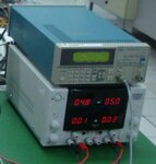
SG and PS.JPG

The above diagram is the power supply that I am using.

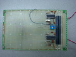
DSC04640.JPG

The top half is my modulator and the bottom half is my demodulator. I can't use the empty space starting from the left most components of my modulator/demodulator as I have a size limit that I need to follow and so the rest of my space is to place my transceiver.

So I am wondering if there is enough space to do the shielding?
 

Amazing...to test a circuit that will be send in space, wired on a breadboard ...hopefully you are not sending the power supply also...
 

Amazing...to test a circuit that will be send in space, wired on a breadboard ...hopefully you are not sending the power supply also...

Ha, this is my first prototype. Of course, once everything is stable and working, I will fabricate it to allow it to be able to work in space. And for the power supply, it is being supplied from the power subsystem in the satellite.
 

All right. I feel more comfortable now. I was scared to get something falling from the sky :)
Try to jump over this stage (using a breadboard) and design the circuit directly on a PCB, and you'll see big difference. Even if may be necessary to do 2 or 3 PCB revisions.
 
  • Like
Reactions: Wql

    Wql

    Points: 2
    Helpful Answer Positive Rating
I am seeing that the power supply and signal generator are professional tools already shielded so they are OK.
Make experiments with the shields I already mentioned. See if you have the same problem with the modulator demodulator shielded.

If the modulator is sensitive to the position in space of your Alinco transceiver then shielding it should make it insensitive to electromagnetic radiation because RF can not penetrate inside good shields.

As a parenthesis: If you put a mobile phone inside an hermetically closed metal pot the strength of the received signal will drop to zero. You will not be able to call the phone, it will not ring. This is shielding, isolation against electric or electromagnetic fields.
 
  • Like
Reactions: Wql

    Wql

    Points: 2
    Helpful Answer Positive Rating
Status
Not open for further replies.

Part and Inventory Search

Welcome to EDABoard.com

Sponsor

Back
Top