Continue to Site

Welcome to EDAboard.com

Welcome to our site! EDAboard.com is an international Electronics Discussion Forum focused on EDA software, circuits, schematics, books, theory, papers, asic, pld, 8051, DSP, Network, RF, Analog Design, PCB, Service Manuals... and a whole lot more! To participate you need to register. Registration is free. Click here to register now.

Explanation about some filter requirements

Status
Not open for further replies.

desk7

Newbie level 4
Joined
Nov 7, 2017
Messages
6
Helped
0
Reputation
0
Reaction score
0
Trophy points
1
Activity points
52
I have to design a filter with the following requirements:
Type Bandpass
Nominal center frequency (F0) [GHz] 12.5 GHz
BW 2 dB [GHz] 12-13
Insertion loss @ F0 [dB] 4.5 max
Rejection band 30 dBc [GHz] [10-11.6;13.4-14.5]
Rejection band 40 dBc [GHz] [16-18]
Rejection band 60 dBc [GHz] [0.1-10;14.5-17]
Return Loss @ BW 2dB [dB] 10 min

Amplitude Ripple in any BW 25 MHz in BW 2dB ± 0.2 dB pK max
Phase Ripple in any BW 25 MHz in BW 2dB ± 2° dB pK max
Nominal impedance [Ω] 50

I can't understand the highlighted requirements because they seems inconsistent.
If 11-12 GHz is the 2dB BW how can S21 go down 4.5 dB at F0? And so on...

Could you explain me this requirements, please?
 

Insertion loss is the loss over the absolute (calibrate your measurement system so that a pass-thru signal with no filter sets up your reference line). Your 2 dB BW is measured from the amplitude of your f0 point.

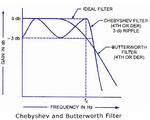
The ripple spec is telling you what type of filter you will need (Butter, Chev, etc).

Pretty normal filter specifications.
 
  • Like
Reactions: desk7

    desk7

    Points: 2
    Helpful Answer Positive Rating
Insertion loss is the loss over the absolute (calibrate your measurement system so that a pass-thru signal with no filter sets up your reference line). Your 2 dB BW is measured from the amplitude of your f0 point.

The ripple spec is telling you what type of filter you will need (Butter, Chev, etc).

Pretty normal filter specifications.
Thanks
So if IL at f0 is 3dB, then the passband must be above -5dB, right?

Could you please explain deeply the last requirements? What means "in any BW 25 MHz"
Is the ripple the maximum range of oscillations or its half?
 

Attenuation@BW2dB=Insertion Loss@Fo+Attenuation @ Corner Frequencies
 
  • Like
Reactions: desk7

    desk7

    Points: 2
    Helpful Answer Positive Rating
Thanks
Could you please explain deeply the last requirements? What means "in any BW 25 MHz"
Is the ripple the maximum range of oscillations or its half?

This means that for any 25MHz slice of the 2 dB passband, the ripple must be less than ± 0.2dB. With this requirement, you should probably start with a Butterworth response, or a low ripple Chevy.

The ±0.2dB requirement is confusing - what reference point do you use? Ripple is usually specified as a peak to peak measurement across your frequency of interest. With the ±0.2dB spec, a +0.1 to -0.3 ripple isn't the same.
 
  • Like
Reactions: desk7

    desk7

    Points: 2
    Helpful Answer Positive Rating
This means that for any 25MHz slice of the 2 dB passband, the ripple must be less than ± 0.2dB. With this requirement, you should probably start with a Butterworth response, or a low ripple Chevy.

The ±0.2dB requirement is confusing - what reference point do you use? Ripple is usually specified as a peak to peak measurement across your frequency of interest. With the ±0.2dB spec, a +0.1 to -0.3 ripple isn't the same.

Perhaps the reference point is f0. If I have understood, that requirement is about the slope in pass band, right?

What I should use as ripple to evaluate the order of a Chebyshev filter, 4.5 or 0.2 or 2?

Excuse me but I'm still a bit confused.

---
Another question: about the impedance, the requirements means that the filter has to be designed with 50 Ohms ports or that Z11 and Z22 of the filter have to be 50 Ohms at f0?
 
Last edited:

Perhaps the reference point is f0. If I have understood, that requirement is about the slope in pass band, right?

What I should use as ripple to evaluate the order of a Chebyshev filter, 4.5 or 0.2 or 2?

Another question: about the impedance, the requirements means that the filter has to be designed with 50 Ohms ports or that Z11 and Z22 of the filter have to be 50 Ohms at f0?

When you are selecting the coefficients of a Cheby filter, one of the inputs is passband ripple, so just enter the requirements there. I haven't looked at the rejection specs of your filter, but I would start with a Butterworth topology.

The impedance at each port is also one of the inputs to the design, so just specify 50Ω at that stage. The filter will maintain an impedance of approximately 50Ω throughout the passband.
 

When you are selecting the coefficients of a Cheby filter, one of the inputs is passband ripple, so just enter the requirements there.

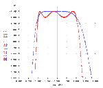
Is the ripple equal to 2dB because BW is @2dB?
I can't understand.
Thanks for your patience
 

Attachments

  • main-qimg-9a3fc4c5afff58de38f67e1a3ab2de89.png
    main-qimg-9a3fc4c5afff58de38f67e1a3ab2de89.png
    128.6 KB · Views: 115
  • es05a.gif
    es05a.gif
    54.1 KB · Views: 118

Status
Not open for further replies.

Similar threads

Part and Inventory Search

Welcome to EDABoard.com

Sponsor

Back
Top