Continue to Site

Welcome to EDAboard.com

Welcome to our site! EDAboard.com is an international Electronics Discussion Forum focused on EDA software, circuits, schematics, books, theory, papers, asic, pld, 8051, DSP, Network, RF, Analog Design, PCB, Service Manuals... and a whole lot more! To participate you need to register. Registration is free. Click here to register now.

580 MHz Lumped Element Bandstop Filter

rf997

Junior Member level 2
Joined
Oct 19, 2023
Messages
22
Helped
0
Reputation
0
Reaction score
0
Trophy points
1
Activity points
156
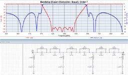
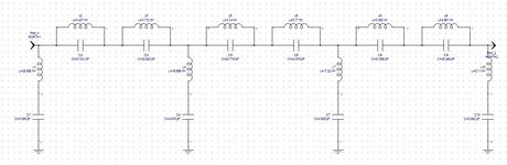
Hello, I am trying to make a lumped element band-stop filter that stops between 470-690 MHz. I designed the circuit with ideal elements as shown in the figure, but in order for it to be produced, I need to insert microstrip lines. However, I need to connect 6 elements at the junction points. What kind of structure should I use here?
1698915375968.png
 
Hi!

You'll have to join it with microstrip Tee (MTEE at Microwave Office) and short microstrip lines. Be cautious, you have to simulate also the parasitics of the real inductances and capacitances, because it changes your response. Sometimes the manufacturers give you those touchstones files.


By the way, you have to use componentes with a series resonance higher that your frequency of operation. Take into account power ratings of your filter too, in order to void burning componentes.

Regards
 
In addition to psach17's comment: you need to carefully include all your routing, to calculate parasitic L and C. In your screenshot it is difficult to read all values, but you have some 0.x pF capacitors and the SMD pads can easily add parasitic shunt C of similar size.

I am afraid that your design will break once you include real component data (S2P) and layout parasitics and tolerances.
 
Last edited:
Microstrip Lines are not common for this band because of their lengths.
Also, you filter is so complex consequently it will be very sensitive to tolerances and manufacturing tolerances. It will bring so many troubles to you.
If I were you, I would simplify this filter with few components
 
Always when I design an LC filter I try to avoid placing two (or more) identical LC resonators in parallel, as you did.
Placing them in parallel doesn't help much in filter performances, but problems related to parasitics increase exponentially.
This you can see in the simulation when use the provided S-parameters from L and C manufacturers.
 
Always when I design an LC filter I try to avoid placing two (or more) identical LC resonators in parallel, as you did.
Placing them in parallel doesn't help much in filter performances, but problems related to parasitics increase exponentially.
You get this topology when designing chebychev II or elliptic band stop. Resonance frequencies are sufficiently separated not to interact.

The alternative 1st element shunt implementation gives more handy C values, BTW.

1699015650783.png

--- Updated ---

The parallel resonators in the original topology can be connected through double-T, one up, one down.
 
A less complex filter with practical components. Inductors are form Murata, Capacitors are from AVX (Kyocera).
As I said earlier, I have designed many this type of filters with discrete components and tolerances are troublesome. Therefore you have to choose/select carefully the tight tolerance components otherwise the circuit may become very heavy headache.
Series resonance circuits (notches) here are important because mid-point of this circuits are very sensitive to parasitic effects. therefore your have to minimize layout effects for these nodes.
-Do not lay out the inductors very close/coincidence and coaxial Instead, lay them out by 90 degree if possible.
Layout is important.
1699019683786.png

1699019103481.png
 
I would think that the wavelength is about 2ft and tlines within
the filter-gang would not be necessary - just make it optimally
tight (so shunt-C and coupling-C / inductor mutuals are at a
happy place, not too close and not too widely spaced)?
 
You get this topology when designing chebychev II or elliptic band stop. Resonance frequencies are sufficiently separated not to interact.

The alternative 1st element shunt implementation gives more handy C values, BTW.

View attachment 185950
--- Updated ---

The parallel resonators in the original topology can be connected through double-T, one up, one down.

I used many filter synthesis programs, one better than other. But none of them use two (or more) series LC resonators placed in parallel (whatever topology chose). I don't say you can't, but is not the right choice when you have to deal with parasitics and tolerance issues.
 

Attachments

  • Cauer_BSF.jpg
    Cauer_BSF.jpg
    219.1 KB · Views: 41
I was actually trying to ask that how to connect the elements together after designing the circuit with lumped elements.

My Design Plan:
1-Designing the circuit with ideal lumped elements
2-Find the elements closest to the ideal values from the vendor library and replace them with ideal elements
3-Performing discrete optimization with mdif files containing real s parameters for capacitor and inductor values
4-Adding microstrip lines as shown in the figure and finding the length and widths of the microstrip lines through optimization(The lengths and thicknesses of the lines are representative.

However, I couldn't be sure whether I will be able to connect the first circuit I made with microstrip lines in this way or not.

Note: The reason why I use a 9th order elliptical filter is that the s21 value of the filter should show a very sharp decrease between 450-470 MHz. For example, if there is 2 dB insertion loss at 450 MHz, it should decrease to around 40 dB at 470 MHz


1699050473835.png

1699050519962.png
)
--- Updated ---

I used many filter synthesis programs, one better than other. But none of them use two (or more) series LC resonators placed in parallel (whatever topology chose). I don't say you can't, but is not the right choice when you have to deal with parasitics and tolerance issues.
I made the filter using the iFilter wizard in AWR. There were no other options for the Bandstop lumped elliptic filter. The purpose of using an elliptical filter was that I wanted a sharp transition from 450 MHz to 470 MHz. Is there another filter design tool you can recommend?

Capacitor units in the figure are pF and inductor units are nH.

1699051184621.png
 
Last edited:
At least FilterSolutions gives you the options of 1st element series (your filter) and 1st element shunt (post #7, #8 and #10).

It's reasonable to model PCB parasitics, the dimensions in your sketch don't seem reasonable. I would go for small L and C chips (e.g. 0402) and traces not longer than necessary for magnetic decoupling. Trace L and C can be modeled as lumped elements.
 
I noticed a mistake in your initial design: C3 uses a fixed value of 1pF. You made a mistake and assigned the variable to the component ID.

C3_mistake.png


Regarding Filter Solutions (formerly Nuhertz, now Ansys): I agree this is the best solution on the market. It can design for real components, which is important, and gives a lot of topology choices.

Maybe BigBoss can jump in and see if your specs are possible at all, using real components in an ideal layout case (no layout parasitics). In #8 there is a solution that seems close to your stopband specs?
 
Note: The reason why I use a 9th order elliptical filter is that the s21 value of the filter should show a very sharp decrease between 450-470 MHz. For example, if there is 2 dB insertion loss at 450 MHz, it should decrease to around 40 dB at 470 MHz
Dear rf997,

Your request is too tight for this filter, its' specifications are indeed very troublesome. Why ??

-Some filter components will have weird and extreme values.
-The tolerances will play very important role on the filter's response.
-You request 40dB attenuation in a 20 MHz steep. It's not reliable even with BAW/SAW filters.
-Even you increase the order of the filter, this won't be available and insertion loss will raise to nonsense values.

I recommend you to loose the specifications then consider more practical values.
First of all, thank you for your advice. I am a university student and I am doing an internship at a company. I was asked to make a filter that meets these requirements. But it doesn't seem possible for me to do this. I will try loosening the requirements and lowering the degree of the filter as you said.
 
The Band Stop Filter proposed in #10 was designed with filter syntheses solution of Genesys software (part of Keysight now), which myself I consider the best filter design solution on the market.
The program was developed by the previous owner of Eagleware/Genesys software, Randall Rhea, a famous RF/Microwaves publisher.

The designed band stop filter use convenient LC values and provide good performances.
 

Attachments

  • Band_Stop_Filter.jpg
    Band_Stop_Filter.jpg
    103.9 KB · Views: 35
The Band Stop Filter proposed in #10 was designed with filter syntheses solution of Genesys software (part of Keysight now), which myself I consider the best filter design solution on the market.
The program was developed by the previous owner of Eagleware/Genesys software, Randall Rhea, a famous RF/Microwaves publisher.

The designed band stop filter use convenient LC values and provide good performances.
Is this program paid? If it is paid, are there any programs that design with real components where I can use the student version or trial version?
 
Ansys offer a free trial for Filter Solutions (now Ansys, formerly Nuhertz).

This tool can synthesize the best possible filter using real components, i.e. existing values from a manufacturer series that you can choose, and includes the component parasitics by using S2P data for each component. This means the filter synthesis result is already close to reality. Not sure if there is any feature limitation in the demo version.

In my opinion, a filter synthesis tool that uses ideal values (as shown in #16) and ignores component parasitics is rather useless for this application, because it will give you some result that can't be manufactured in real world.
 
By default Genesys already have a big library of passive models from various manufacturers.

Major passive manufacturers provides passive models for Genesys. Modelithics also provide a long list of models for Genesys.

Using ideal RF components, is the first step in any filter design, because they are easy to tune and will give to the designer an idea about geting the filter performance for a given number of poles.
Substituting the ideal components in Genesys with their models is just a simple drag-and-drop situation.
 

LaTeX Commands Quick-Menu:

Similar threads

Part and Inventory Search

Welcome to EDABoard.com

Sponsor

Back
Top