Continue to Site

Welcome to EDAboard.com

Welcome to our site! EDAboard.com is an international Electronics Discussion Forum focused on EDA software, circuits, schematics, books, theory, papers, asic, pld, 8051, DSP, Network, RF, Analog Design, PCB, Service Manuals... and a whole lot more! To participate you need to register. Registration is free. Click here to register now.

Explain working of Positive clamper

Status
Not open for further replies.
Joined
Dec 4, 2012
Messages
4,280
Helped
822
Reputation
1,654
Reaction score
791
Trophy points
1,393
Location
Bangalore, India
Activity points
0
Please explain the working of the unbiased Positive clamper circuit shown here.

**broken link removed**

From t0 to t1 the C charges to Vm say (Vm = Vi - 0.7V)

Vm is -10V for ideal diode.

Now Voltage from + side of C to gnd is +10V

Now Vi increases from -10 to 0V during t1 to t2

I want KVL for this condition that is when t = t1 to t2 (as diode anode is still +Ve and left side of C is still -Ve)
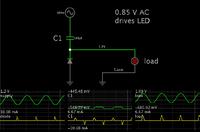
 

I have seen this referred to as the Villard cell. It is the building block for a class of voltage multipliers.

Notice if you attach a load across the capacitor, you would have an ordinary half-wave power supply.

In this case, however we attach the load across the diode. The diode displays a wide voltage swing (occupying one polarity, mostly).

The capacitor is a charge-pump. It is charged when current goes in one direction. When current goes the other way, the supply voltage is added to the capacitor charge. This boosts the volt level which is available for applying to a device.

Example, driving an led from an AC supply whose amplitude is less than the forward voltage of the led.


By adding a peak detector (diode and smoothing capacitor), it creates a voltage doubler. (As shown on page 2 following your linked webpage.)
 
Status
Not open for further replies.

Part and Inventory Search

Welcome to EDABoard.com

Sponsor

Back
Top