Continue to Site

Welcome to EDAboard.com

Welcome to our site! EDAboard.com is an international Electronics Discussion Forum focused on EDA software, circuits, schematics, books, theory, papers, asic, pld, 8051, DSP, Network, RF, Analog Design, PCB, Service Manuals... and a whole lot more! To participate you need to register. Registration is free. Click here to register now.

Embedded system with 250+ IO?

Status
Not open for further replies.

bulletbolt

Newbie level 4
Joined
Aug 5, 2018
Messages
7
Helped
0
Reputation
0
Reaction score
0
Trophy points
1
Activity points
59
Hello all,

Looking for people opinions on how to implement embedded solution with 250+ IO's.

The system would work in such principle that one pin is set to output while all others are inputs. Then it changes to next pin being output and all others inputs.

Looked at IO expanders and potentially using multiple MCU's, but what are your thoughts?
 

Hello,

few years ago i also had a task to make controller for simple I/O control (it was about 200 I/Os). First I was going to implement the system using big PLC ans several I/O extending modules, but price for this solution was too high.
Ultimately I made this controller using MCU STM32F767Zi and several ICs MCP23017 (I2C port expanders). Of course I designed dedicated PCB for this solution (it was qutie big). The large number of transoptors had been used for isolating inputs. From few years it is used on large sea-going vessel and clients didn't report any issues.

Best Regards
 
Analog would be preference, but if too complicated, digital would be fine too.

Voltage and current is not quite applicable, as it effectively checks connections in the cables and some cases diodes, so ~5VDC is more than enough.

Timing is not too critical too.
 

Hello
Voltage and current is not quite applicable
it sounds like a continuity test.

If so, or something similar, for sure it needs some voltage and some current to work with.
--> And I strongly recommend to consider both and additionally timing.

A cable surely is highly capacitive.
Thus - on the output - you need to drive some (non zero) voltage and current to charge/discharge the capacitance within a given timing. And I even guess you need to limit this current in case of cable short circuit.

Also you can´t leave the "inputs" floating, otherwise you get meaningless result.
So at the input you
* need to draw some current you
* need to wait some time then you
* need to validate whether the voltage now is HIGH or LOW.

*****

You say "5V DC is more than enough".. but I guess you need to drive at least two levels like <0.5V / >4.5V and you need to sense <1V and >3V .. just as examples. DC 5V means continously 5V, never anything else.

Most nowadays systems don´t use 5V anymore. Many work with 3.3V supply or less.
So if you say "5V is more than enough", then 3.3V is not included.

I don´t know your requirement, but if you are happy with 1.8V signals, then you should say "1.8V is enough". Then 3.3V as well as 5V is included.

*******

You are free to design the hardware your way... you may do it trial and fail...

My thoughts:
* since cables may be seen as capacitors.. you don´t know the initial voltage. --> you need some ESD protection otherwise your outputs and/or inputs may be killed.
* you say "preferably analog". But mind that many OPAMPS are not able to drive (large) capacitive loads.
* logic ICs may cause or suffer from EMI/EMC

Klaus
 
Last edited:

Most modern processors can config a pin to be bidirectional. Using internal
pullup pin can drive out, and its input register read the pin by driving a 1 onto
pin and reading if its being pulled down by external driver.

Note in some parts pin can function both as analog and digital. Leads to some
interesting design possibilities.

1626270157398.png


Regards, Dana.
 
Last edited:

hello,

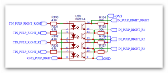
for isolated inputs (with 3.3V logic MCU) one can use transoptors - see schematics:


inputs01.png


and for steering 24V DC relays - for example transistors arrays (for example ICs ULN2603A) - see schematics:

Outputs24relay_.png


Of course sometimes much more sophisticated inputs and outputs are required, but in many situations such simple ones are OK.

Best regards
 

Attachments

  • inputs01.png
    inputs01.png
    38.3 KB · Views: 106

Hi,

ULN2803A circuit:

May I ask what the diodes on the input side (base) are for?
And what is D4 for? It´s not clear to me. On the right label it says "Relay", but.. how are the relays connected?

Klaus
 

Hi,

ULN2803A circuit:

May I ask what the diodes on the input side (base) are for?
And what is D4 for? It´s not clear to me. On the right label it says "Relay", but.. how are the relays connected?

Klaus
Hello Klaus,

it is very basic security in case of on the ULN2803A input appear too high voltage (for example in case of transistors failure).

Best Regards
 

A cautionary tale: Many moons ago I inherited a project that used a similar boundary tester. It was a bed of nails that probed the pins on a connector box. I can't remember the exact details but it has something like 50 pins and they were driven one at a time with all the others monitoring for connectivity. The tester was allowing fails to pass through as good. The software writer (not me I hasten to add!) made the driving pin go to a low logic voltage and scanned all the other pins to check for presence of a voltage. Of course, it would pass even if no device was present at all.

Brian.
 

Something I'd expect you pick up during validation/verifications stage of your project, but yes, software will be key..
 

Status
Not open for further replies.

Similar threads

Part and Inventory Search

Welcome to EDABoard.com

Sponsor

Back
Top