Continue to Site

Welcome to EDAboard.com

Welcome to our site! EDAboard.com is an international Electronics Discussion Forum focused on EDA software, circuits, schematics, books, theory, papers, asic, pld, 8051, DSP, Network, RF, Analog Design, PCB, Service Manuals... and a whole lot more! To participate you need to register. Registration is free. Click here to register now.

Electronically variable resistor

Status
Not open for further replies.

Dimitris Tsiotas

Newbie level 2
Joined
Oct 27, 2013
Messages
2
Helped
0
Reputation
0
Reaction score
0
Trophy points
1
Activity points
16
Voltage variable resistor

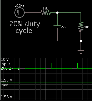
hello I need a voltage variable resistor. I want to build this frequency meter but without using the ampere-meter. Instead, I want a 50k resistor to be controlled by the current that goes into the ampere-meter. what should I use?
Thanks! 2009618205348204.gif
 
Last edited:

The meter needle has some inertia. It averages out the pulses from the 555 IC, to give a steady reading.

If you want a steady voltage across your 50k resistor, proportional to the incoming frequency...

Then the easy way is an RC network.

Screenshot:

8516300800_1382918708.png


If you want linear response, you'll need to play with the values. It depends on how low a frequency you wish to measure, and what duty cycle comes from the 555 output.
 

    V

    Points: 2
    Helpful Answer Positive Rating
Hello thank you for replying and thanks for your suggestion it ιs most useful. Say we have a proportional voltage to the frequency using an rc circuit, how will I then turn that voltage into resistance? more accurately the frequency that I intend to measure ranges from 70hz to 1,5khz which I want to turn into resistance 0 to 50kΩ, where each time 70hz will enter the circuit 0Ω will be measured and as the frequency will raise the resistance will also.
Thank you
 

It sounds like you want the resistance to be linearly proportional to the voltage. That is very hard to do. Why do you want an output resistance anyway? Normally meters and sensors of all kinds are either voltage output or current output. It is very common to have an instrument like this produce a current in the range of 4ma to 20ma. They are called current loop outputs. They are something like a variable resistor as you described, but not really. They would produce more "resistance" as the voltage went down.
 

Hello thank you for replying and thanks for your suggestion it ιs most useful. Say we have a proportional voltage to the frequency using an rc circuit, how will I then turn that voltage into resistance? more accurately the frequency that I intend to measure ranges from 70hz to 1,5khz which I want to turn into resistance 0 to 50kΩ, where each time 70hz will enter the circuit 0Ω will be measured and as the frequency will raise the resistance will also.
Thank you

Hi current to resistor is BJT and Voltage to resistor is FET. Do the above circuit and cascade it with the Transistor to have a resistance....
 

Status
Not open for further replies.

Similar threads

Part and Inventory Search

Welcome to EDABoard.com

Sponsor

Back
Top