Vermes
Advanced Member level 4

It is a system of automatic opening/closing window blinds. The device consists of two processed mini servomechanisms and quite simple driver with full open/close detector.

Servomechanisms were chosen due to the fact, that they are perfect for application in automatic process of opening/closing the blinds. Another advantage is that they are small but provide enough power. Angle of rotation (190 degrees) was achieved by removing the lock and unnecessary electronics. Tower Pro SG-90 servomechanisms were used. Their weight is only 9g and their dimensions are: 22x11,5x27mm. When you remove the electronics from the inside, a small ceramic 100nF capacitor, rectifier bridge and 3mm blue diode with resistor fit in it. The diode provides nice look of the blue lighting housing, which gives an interesting effect in the dark.


Mechanical part:
Firstly, you should intervene the construction of blinds and adapt them to the servomechanisms, especially when it comes to locking the system after reaching the position of open/close. Cord to the blinds are still part of the construction, because they indicate the position of the blinds and in case of a power failure you can open the blinds manually.
Cut the base of the gear clip and after drilling it, paste concentrically inside it part of the lift encroaching on the servo shaft. Mount and screw that part to the shaft.


Then in the part holding everything on the window frame by a hanger, cut a shape of front of the servomechanism, as shown in the photo. Then drill holes holding the servo in place.

Then from a shaft going into aluminum tube, on which there is the blind, cut a „moon”, in which you can hide the cord. It would not be necessary anymore in that place, but it would be useful in other place.

Glue it into a place visible in the picture, so it does not allow the cord to skip on teeth of the shaft. It is very important so you must add enough glue.

Put the unnecessary clip under the cut piece, as shown in the pictures. When everything is assembled, the cord should be hidden behind cut element as previously, but it should be immobile.


When the glue is dried, put everything in place and screw together. Test the operation and set the cord in a position, in which after the blind going up in the maximum position, the cord is blocked by glued element.


Such limiter would be useful when you have blinds in the other room. The limiter should be mounted in a place, in which it blocks the blinds. If you do not have a limiter, shorten the cord properly, so a single limiter block the blind from one and the other side.

Then make a drive for the rest of automation process.
Two relays with two coils each from TYCO RELAYS, model V23084-C, used in car systems of opening and closing windows, there is the note sheet: LINK.

You should create your own flip-flop using 4001. It is important that the system should not enable the second coil after enabling the first coil of the relay. This means that operation of one flip-flop block the other, it must be possible to reset both flip-flops, no matter which is active. Further part of the system is LM339 voltage comparator, which was chosen because it can operate at a voltage close to zero and can be powered by a single voltage, on 0,1 ohm resistors there is a drop of voltage taken by servo. That voltage is compared with the voltage set by potentiometer. In addition, there is a 100nF capacitor, so the voltage drop when starting the second blind does not cause any distortion. When the blind reaches the desired position and the servo is blocked, voltage on the resistor immediately increases and the flip-flop is zeroed, the relay is turned off. By adding a simple differentiator circuit, you can solve the problem of turning on the servo, when a current pulse switches it off immediately. Additionally, STOP button allows you to stop the blind in any position. Basic application LM317 provides regulated voltage source for servos, in which you can set operation voltage – speed.


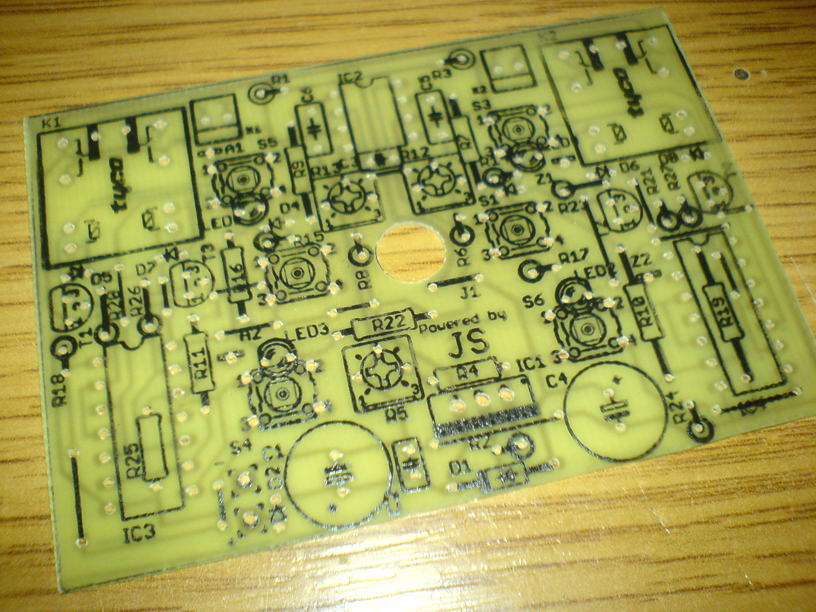
Following pictures show the process of making PCB:
Housing:

Paths, description, mask:


PCB and place of ironing:


Etching, tin plating, drilling:


Covering with mask and description of elements:


Assembly:


Housing was made of clear plastic and fits the PCB with dimensions of 77x54mm. Diodes are placed above the buttons, so when you press a diode – you press the button and light the diode. There is a print on self-adhesive foil, after the ink dried, you should glue another print and one more layer of foil.


The system is powered from a 12V power supply with a capacitance of 1A.
**broken link removed**
**broken link removed**
Link to original thread (useful attachment) – Elektryczne Rolety by JS