Vermes
Advanced Member level 4

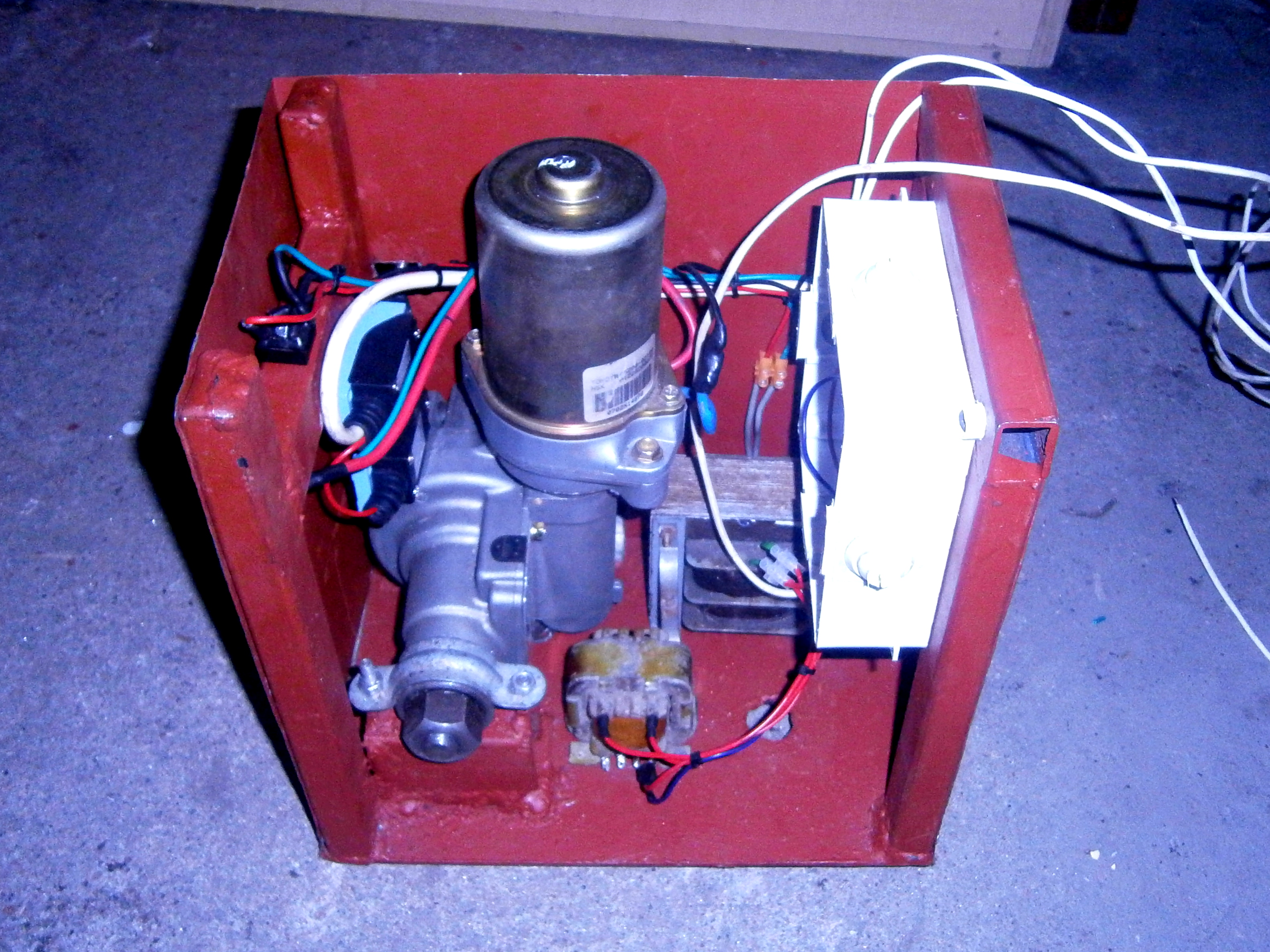
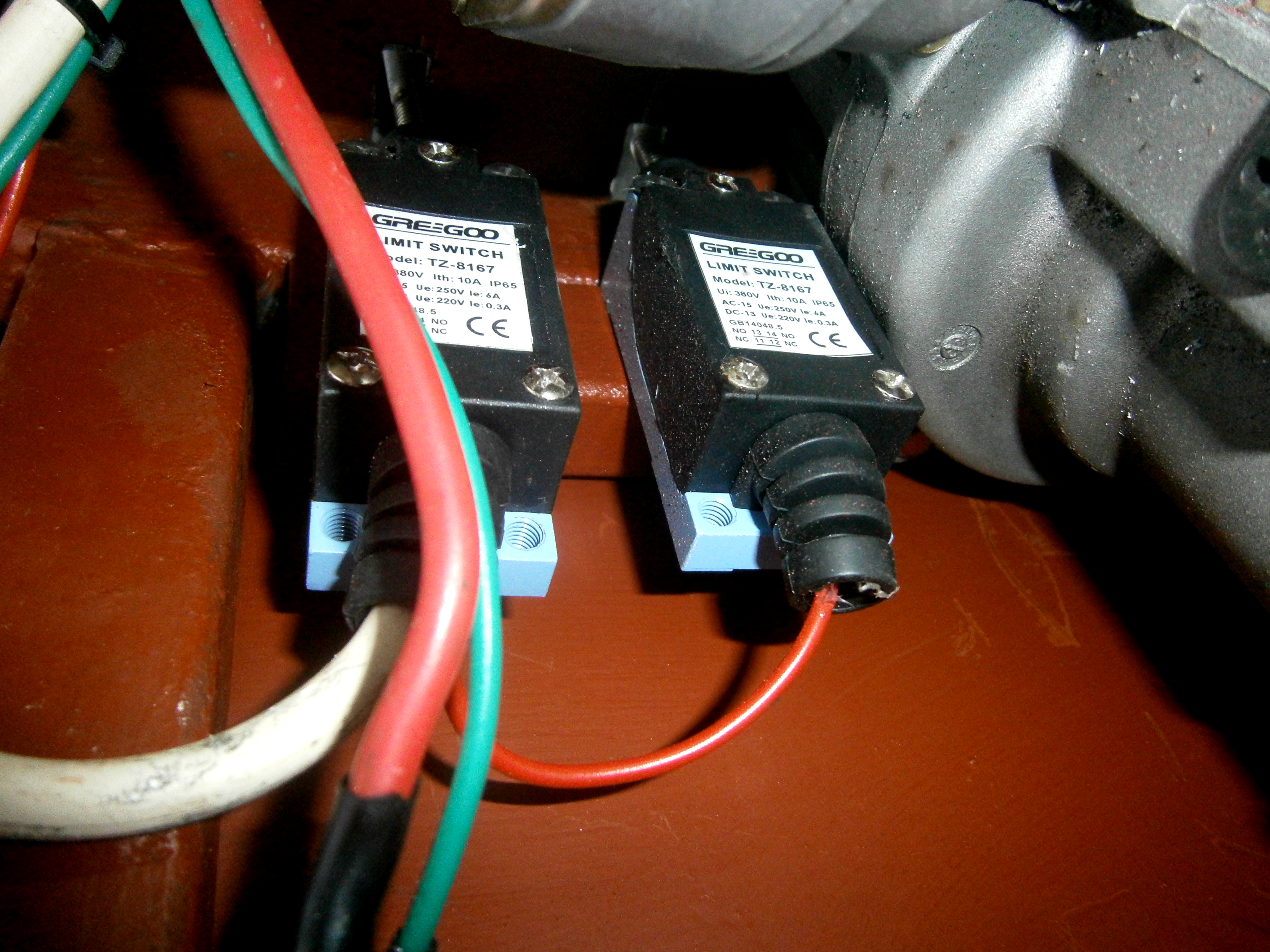
This drive can be used for controlling the gate. Engine with steering column was removed from electrical support from Toyota Corolla. You will also need a driver, gear bars and gear wheel, limit switches and profiles, as well as plate for the housing in form of a box.
Firstly the column was milled and shorten to fit the construction. Next, using a welder, grinder, drill and other tools, you should create the box (housing). It was made of steel profiles 20x30mm and 2,5mm plate. The drive is equipped with a lock that lowers it in the case of loss of power. If you need it, the gate can be opened using bare hands. Then the electronics was mounted.
Pictures of box with electronics and after assembly:
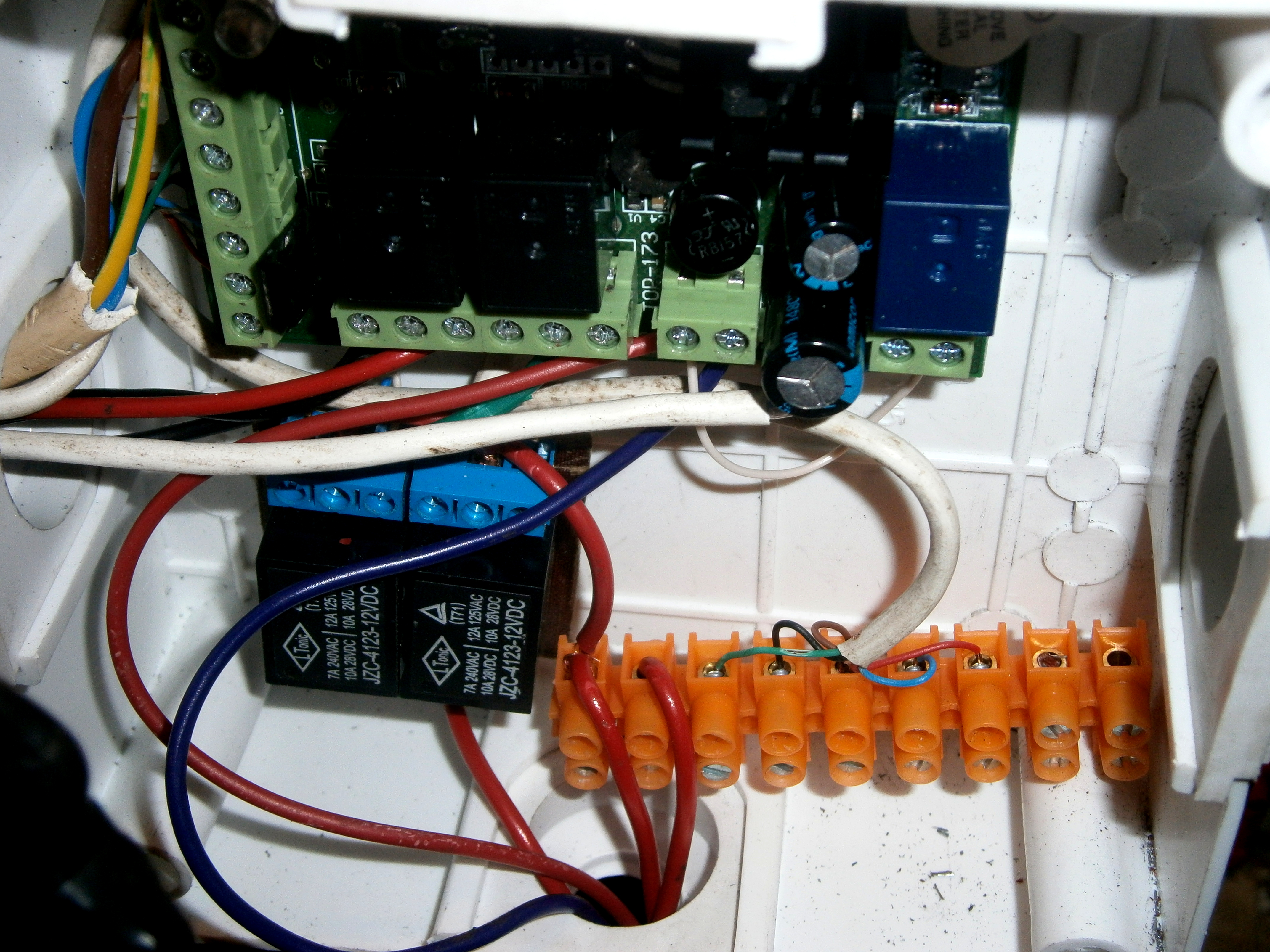
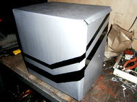
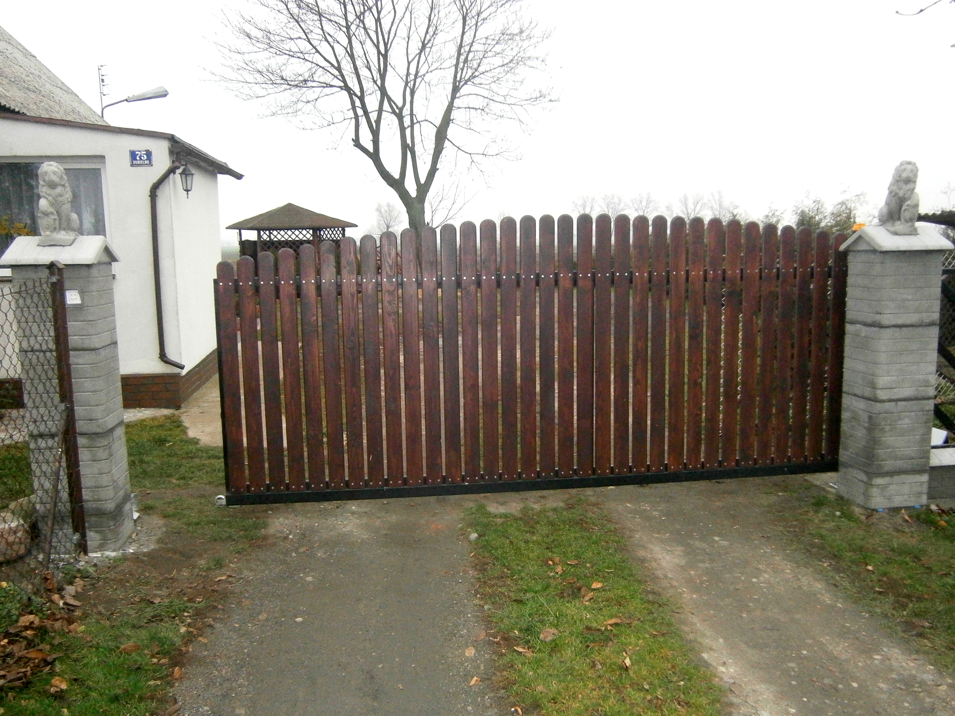
Electronics was put into the hermetic box. Then the housing was painted in color of aluminum with black strips.
When the gate moves too quickly when you run the device for the first time, the solution for this problem is to rewind some turns from the secondary winding until everything is okay. Indicating lamp was made of turn signal from a trailer with five LEDs mounted inside.
The device was also improved by some extra features. There are two transformers and additional relays near the driver. After switching the relays on the driver board, the two additional relays are switched on. They pass voltage to the large transformer that powers the engine. It causes that the engine is not under the voltage all the time. A small transformer is connected permanently to power the circuit. Thanks to that, the device is very energy saving.
Remote control range is about 30m. Additionally you can mount a button for manual opening or closing the gate, which can be placed at home.
Pictures:

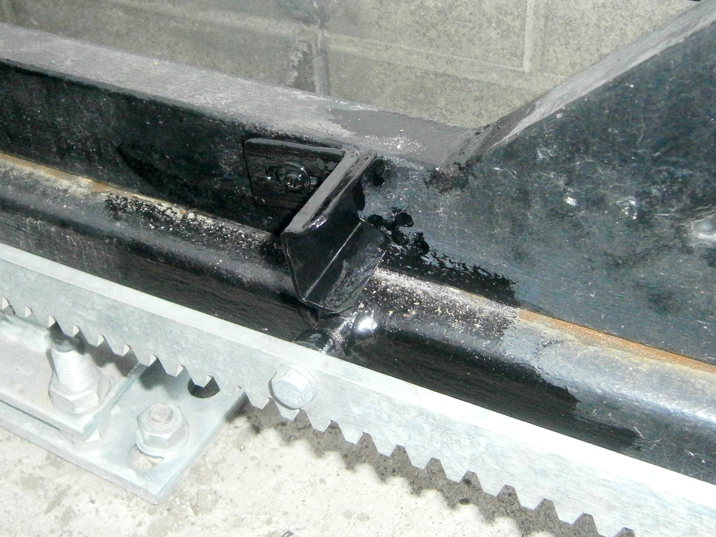
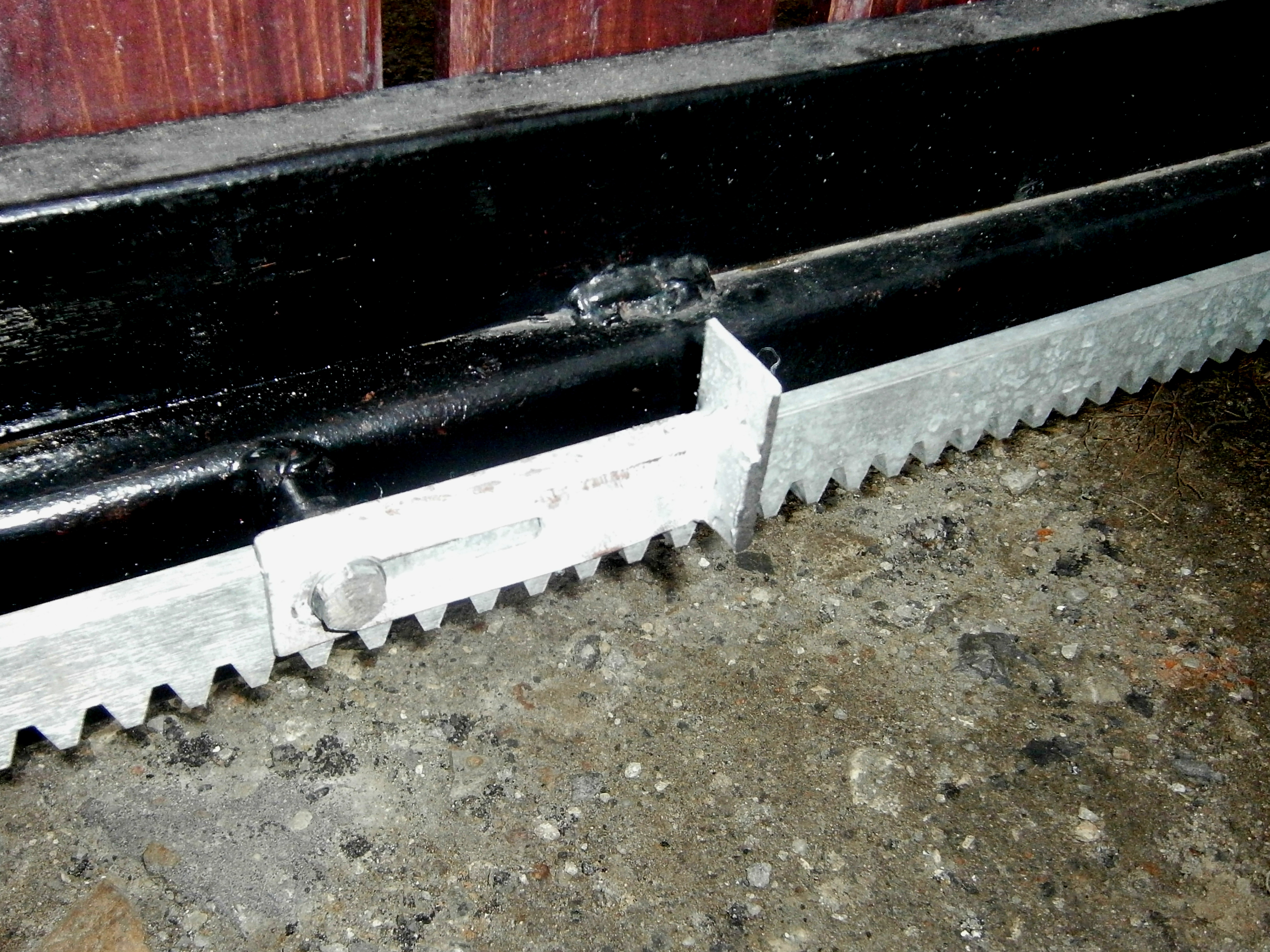
Picture of the base to which the upper part is mounted:

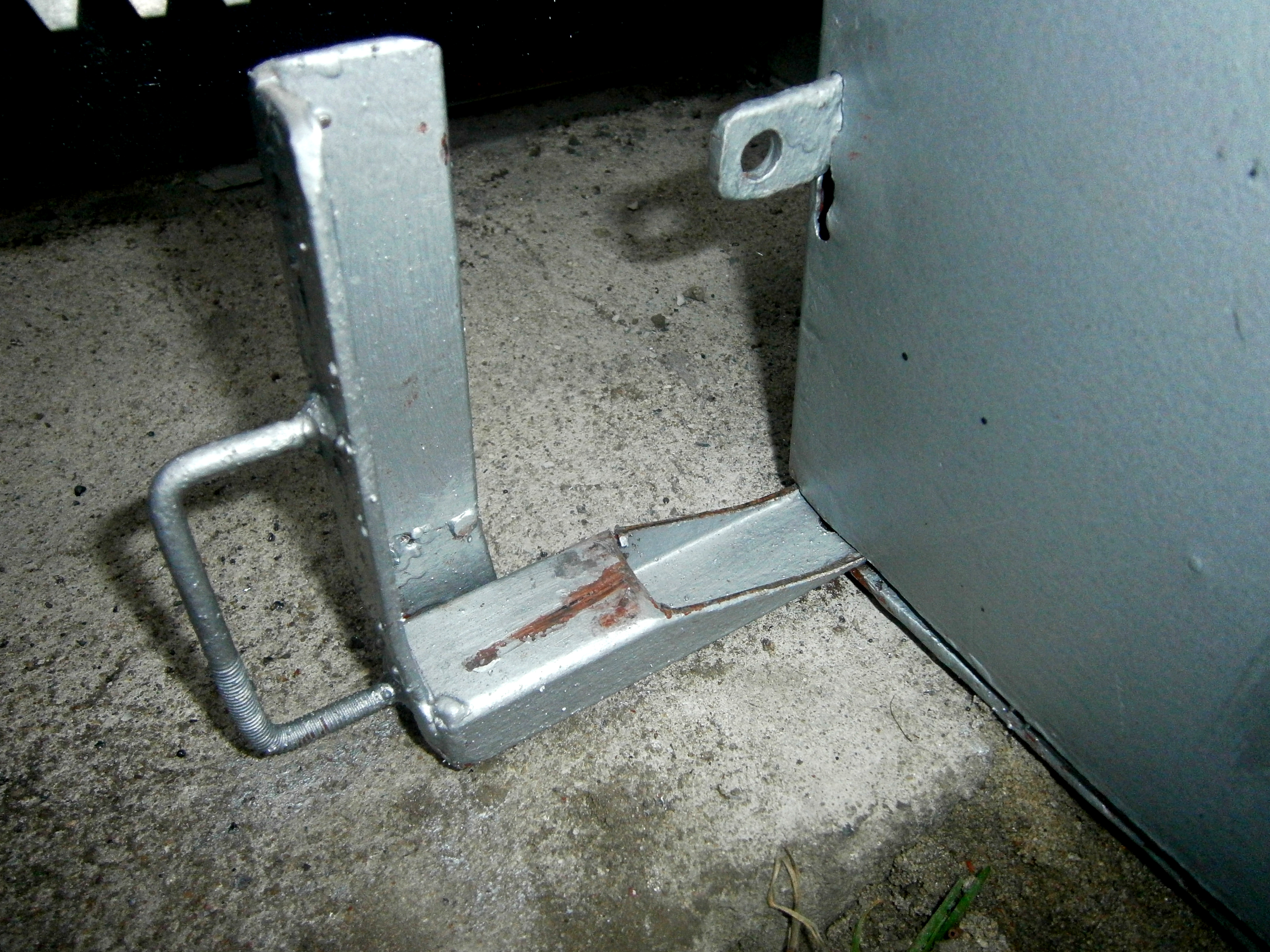
Handles for switching the limit switches:
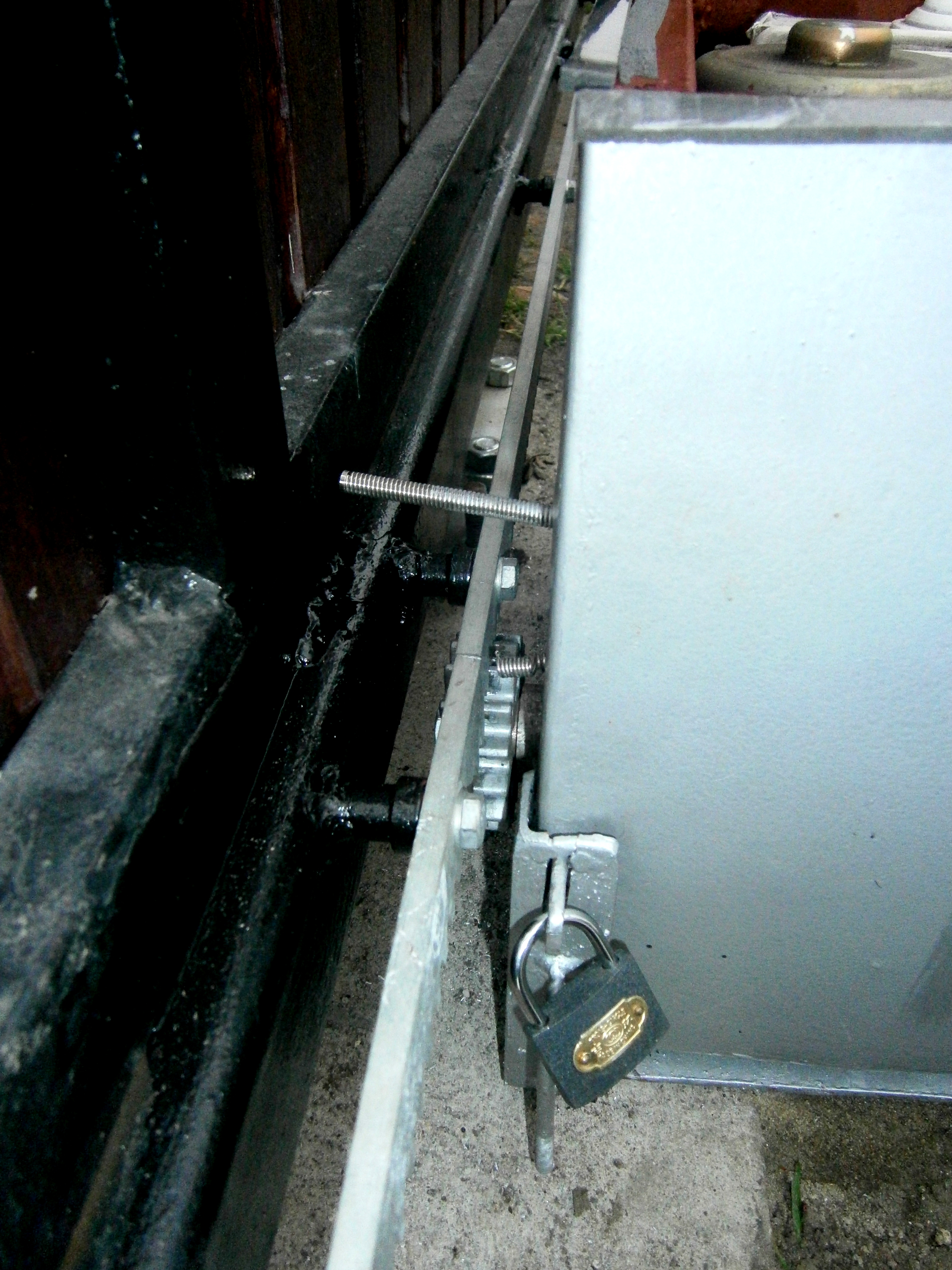
Lowered drive – the gate can be moved then:
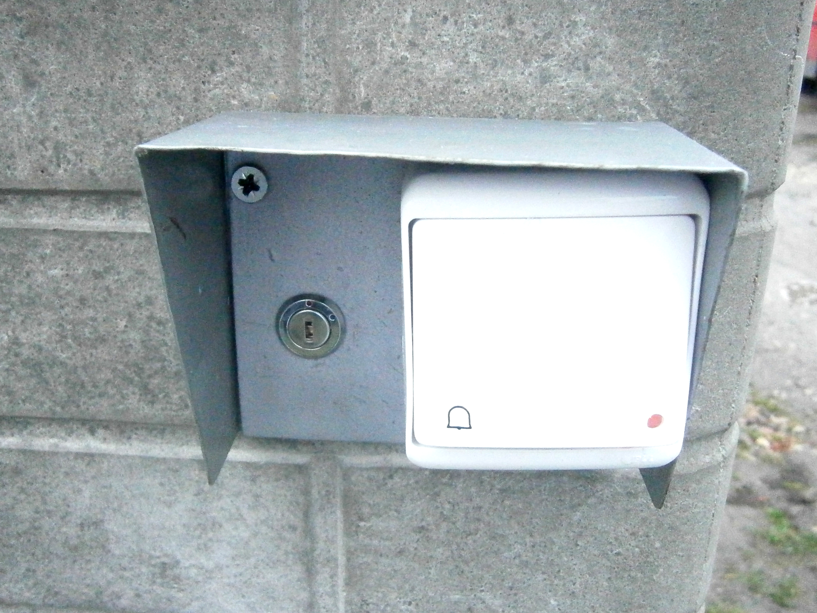
Key switch and switch to the ring:
Link to original thread - Napęd bramy przesuwnej według własnego pomysłu