Continue to Site

Welcome to EDAboard.com

Welcome to our site! EDAboard.com is an international Electronics Discussion Forum focused on EDA software, circuits, schematics, books, theory, papers, asic, pld, 8051, DSP, Network, RF, Analog Design, PCB, Service Manuals... and a whole lot more! To participate you need to register. Registration is free. Click here to register now.

Efficiency and gain graph VS input power

Status
Not open for further replies.

mohamis288

Full Member level 3
Joined
Mar 1, 2022
Messages
164
Helped
0
Reputation
0
Reaction score
1
Trophy points
18
Activity points
1,235
Hi,
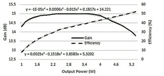
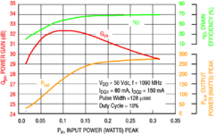
In the following, I have attached 2 images related to 2 different power amplifier. efficiency and power gain is approximately the same for all of the RF power amplifier. can someone explain about why does power gain has a peak?
 

Attachments

  • ic2.jpeg
    ic2.jpeg
    68 KB · Views: 142
  • ic1.png
    ic1.png
    180.9 KB · Views: 146

Solution
Because after the peak by increasing the input you won't receive that much increase in output. because the PA goes to saturation. you can find it from the orange curve. you should make a compromise between Gain and Efficiency and based on these two factors choose your operating point.
Also before the peak, we can say that transistors inside PA are not entirely on, and after a level of input, they are at their best operation point.
 

    mohamis288

    Points: 2
    Helpful Answer Positive Rating
Solution
This phenomenon is named Gain Expansion and appears only in nonlinear PAs (Class-AB, Class-C, etc.), where the active device is biased (more or less) by the RF input power and not (only) by the DC bias.
Increasing the RF input power, the gain gets higher and higher up to the point where the PA saturates and its gain starts to decrease vs input power.
In linear PAs (e.g. Class-A) where the PA is never in saturation, the gain of the PA is (faithfully) constant vs RF input power.
 
Power Gain curve is NOT a typical one. It should be flat up to a certain value then it drops.
But this is different. There ought to be an explanation.
The test methodology might be different or modulation based.
 

Status
Not open for further replies.

Part and Inventory Search

Welcome to EDABoard.com

Sponsor

Back
Top