Continue to Site

Welcome to EDAboard.com

Welcome to our site! EDAboard.com is an international Electronics Discussion Forum focused on EDA software, circuits, schematics, books, theory, papers, asic, pld, 8051, DSP, Network, RF, Analog Design, PCB, Service Manuals... and a whole lot more! To participate you need to register. Registration is free. Click here to register now.

editing dVce time constant

Status
Not open for further replies.

deniz88

Member level 2
Joined
Jul 28, 2009
Messages
47
Helped
0
Reputation
0
Reaction score
0
Trophy points
1,286
Location
germany
Activity points
1,703
Hi,

i want to measure dVce/dt,
for that i used a differential amplifier(i need Vce too), after that i put a RC circuit to get dVce

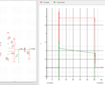
problem is, dVce peak value change too fast, ADCs are soo expensive. changing RC doesnt help because output of the opamp change to fast. Circuit looks like on the picture.

i didnt use peak detector, because it needs many components, two opamp, schotky diode, cap, resistor and mosfet to discharge the capacitor.
Maybe anyone can suggest a better solution in such case, dUce.PNG
best regards
 

Do you need to differentiate over a wide bandwidth in number of decades?

Do you want to separate negative edges from positive edges? Then use a fast analog switch with a low leakage current OpAmp to make a Sample and hold. The sample would be controlled by a fast comparator and held until before the next sample. More input on function needed.

In other words , a wide range of slew rates over a period of time or just the transient edges?

Then you need the RC active differentiator with very low leakage current and low leakage plastic film caps.

Is this to measure an IC slew rate faster than your scope? Just use a passive RC with a break point well below (<1/10th) your commutation rate and and choose C much greater than your load capacitance with and ESR much lower than the load resistor.

There are lots of solutions . First define the inputs and desired DC outputs and timing.
 

Hi,

An RC is never a true differentiator (nor integrator).

You really need to define your signals.


With a square wave input...dU/dt is infinitely high at the edges, and zero all the other time.... but obviously you don't expect an infinitely high output voltage?

What do you expect?

Klaus
 

Hi SunnySkyguy,

thanks for the answer,

Do you need to differentiate over a wide bandwidth in number of decades?
yes i need to measure it every cycle, so every 0.5khz


Is this to measure an IC slew rate faster than your scope?
it is to measure, voltage increase and decrease of the igbt

- - - Updated - - -

Hi KlausST
With a square wave input...dU/dt is infinitely high at the edges, and zero all the other time.... but obviously you don't expect an infinitely high output voltage?

What do you expect?

it is the voltage of an igbt during the switching, my purpose is measuring the dVce/dt and -dVce/dt during the switching.

best regards
 

Hi,

you want to measure dV/dt.

please specify your max expected dV/dt

during switching....this means there is not much time...not easy


Klaus
 

Hi KlausST
i expect max 4500V, i used a voltage divider to make it 1000 times smaller, (on the simulation it is 2900V)
after the opamp, i added RC to get derivation.
but, problem is , rc doesnt stay on peak value long like on the graph.
thank you
 
Last edited:

Hi,

dV/dt is not in "V" maybe in "V/us". Clarify this.
Not "volts" but "volts per time"

Klaus
 

deniz88

What are you really measuring? +ve rise time only? overshoot? net result + then - from one transition?

Confirm max Sampling rate.

This does not span many decades of frequency. Maybe you just want to hold value for a long time (2ms) for some reason.

- - - Updated - - -

What is IGBT Voltage range and max desired load for this measurement?

The only way to measure slew rate without adding burden to the source and slowing it down is to use a low capacitance R divider into 50 Ohm LeCroy scope,or equivalent.
The other way is to use a coupling antenna and scale down into 50 Ohm spectrum Analyzer with a repetitive pulse that shows harmonics. By analyzing these harmonics the slew rate can be extracted.
 
Last edited:

Status
Not open for further replies.

Similar threads

Part and Inventory Search

Welcome to EDABoard.com

Sponsor

Back
Top