Continue to Site

Welcome to EDAboard.com

Welcome to our site! EDAboard.com is an international Electronics Discussion Forum focused on EDA software, circuits, schematics, books, theory, papers, asic, pld, 8051, DSP, Network, RF, Analog Design, PCB, Service Manuals... and a whole lot more! To participate you need to register. Registration is free. Click here to register now.

Dual battery charging and power path management

Status
Not open for further replies.

zuirgham

Junior Member level 3
Joined
Mar 19, 2019
Messages
31
Helped
0
Reputation
0
Reaction score
1
Trophy points
8
Activity points
368
Hi TI team,

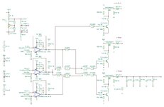
I'm designing Power path control for 3 supplies along with dual battery charging system.

V1= 30V(10A), Vbat1= 29V approx(7-cell in series Li-ion, 3500mAh), Vbat2= 29V approx(7-cell in series Li-ion, 3500mAh).

Design equations:

1. 30V(10A) supply will charge both batteries, But instant-on power to be delivered to system circuitry for operation.

2. Both Batteries can be charged simultaneously or one after the other.

3. Power path with no cross or reverse current conduction.

4. Priority V1 > Vbat1 > Vbat2

5. Switching between supplies without any power interruptions( Preferable 10uS)

Kindly advice for design.
 

1.
Li-on is the type in news reports for causing fires and explosions. Can you discover whether each battery has some kind of built-in safeguard?
Or do your batteries require 'smart' charging?

You ought to install a battery monitor to stop charging when they reach a certain level. And also shut them off when discharged below a certain volt level.

2.
Are you familiar with power switching plugs and jacks used in audio/ video equipment? These automatically route external power or internal battery power. For your power level they must have robust construction.

3.
In some cases steering diodes may be sufficient and you don't necessarily need switches or relays . Simply have the battery send power all the time. When the external supply is present, diodes steer current to charge the battery if needed.

4.
Look at electrical systems for recreational vehicles, to see how they choose between:
* battery power
vs
* external generator
vs
* running engine.
hey mate, you're going in other direction. Apologise for not mentioning this, Battery packs have their BMS PCB installed inside. i'm using similar battery in other projects too. There i'm working with single battery. Battery is all safe to go. So i need not worry more on the internal batteries. I'm designing circuit to charge them and manage the power-path from all 3 supplies. Lets keep it that simple.
 

Hi,

Block diagram of what you need to do, thanks.

[p.s. This is edaboard, not TI's e2e, ;) ]
--- Updated ---

Quick ideas you could ponder and juggle with: AN105 - figures 134, 141, 142. For starters.
 
Last edited:

Hi again zuirgham,

Another quick idea: some comparators + voltage reference(s) + resistive divider, some suitable logic to 'think and decide', e. g. Vref as stable supply for Rdiv to sense divided down threshold voltages (i.e. V1, make e.g. 20V > 2V or 200mV, etc., 30V threshold too high, imo), MOSFETs as power path switches to load. One comparator to see if V1 is present or not, other comparators to judge if bat1 and/or bat2 have sufficient charge to power load if V1 absent, all comparators into appropriate logic, logic decides which MOSFET (power path) to select. Nice to add load overcurrent and short protection stage. Enjoy the truth table part.

That kind of thing is one bulky option, or dedicated power path management ICs is another.

10us is the lesser of your concerns, that is a very long time indeed, a hold-up capacitor or two would cover switching between sources (V1 or bat1 or bat2) - e.g. you can so easily find:
comparator = 200ns to 1 us
logic (e.g. HC) = 20ns to 50ns [* 3 stages for the sake of 'just in case'] = 150 ns
switch (FET) = 50ns to 300ns
Total = probably less than 2us.

Searching yourself for power path management ICs will be the simplest and smallest PCB approach, 'though. From memory (read them a long time ago, so pardon possible error of mine here), TI have ideal diode ICs which I recollect in typical applications in datasheets are used for ORing power paths.
 

And hi again zuirgham,

Here is a schematic of a the non-microcontroller-based solution I described earlier. Apologies for the large jpg... It is only a rough sketch, just the general idea: Zeners needed on PMOS gates, bypassing needed on CD4000 ICs, you'd need to consider inrush current, adapt it to fit V1 charging Bat1 and Bat2. It took some 1800 uF of hold-up capacitance to avoid voltage droop at the load when switching between V1 and Bat1 or Bat 1 and Bat2. There is one comparator left out of a quad package as only three are needed. I was in a rush to get on with the idea and have dinner, so the PMOS is part of a dual P and N package that is a reasonable model (i.e. no special reason for using it) , so maybe instead of the 2N2222A it could be the/an NMOS, or more likely, finding a more suitable PMOS for the circuit. No idea how you'd fit this into V1 charging the batteries but that should be a simple step for you.

In quick simulations at 27ºC only: if V1 is lower than ~20V, Bat1 takes over; if Bat1 is lower than ~28V, Bat2 takes over; if Bat 1 and Bat2 are 29V, Bat1 has precedence. I used CD4000 parts, it still switches from one source to the other in far less than 10us, and there are from 5 to 7 stages (devices) between sensing and output switches, HC parts are about 200ns faster than CD4000 logic devices. FYI: Across temperature range: LM193 = 0.3us to a terrible 1.3us propagation delay; CD4000s = ~225 ns to ~450ns propagation delay; BJT = ~320ns total on and off times, PMOS = ~70ns total on and off times.

If I were any good at coding, I'd do this with an MCU. If you're if not an MCU person, look for power-path management ICs - it would be a much smaller, simpler circuit indeed.

Best of luck with the circuit, whatever you do in the end!
 

Attachments

  • EDA V1 BAT1 BAT2 SKETCH.JPG
    EDA V1 BAT1 BAT2 SKETCH.JPG
    146.7 KB · Views: 109

And hi again zuirgham,

Here is a schematic of a the non-microcontroller-based solution I described earlier. Apologies for the large jpg... It is only a rough sketch, just the general idea: Zeners needed on PMOS gates, bypassing needed on CD4000 ICs, you'd need to consider inrush current, adapt it to fit V1 charging Bat1 and Bat2. It took some 1800 uF of hold-up capacitance to avoid voltage droop at the load when switching between V1 and Bat1 or Bat 1 and Bat2. There is one comparator left out of a quad package as only three are needed. I was in a rush to get on with the idea and have dinner, so the PMOS is part of a dual P and N package that is a reasonable model (i.e. no special reason for using it) , so maybe instead of the 2N2222A it could be the/an NMOS, or more likely, finding a more suitable PMOS for the circuit. No idea how you'd fit this into V1 charging the batteries but that should be a simple step for you.

In quick simulations at 27ºC only: if V1 is lower than ~20V, Bat1 takes over; if Bat1 is lower than ~28V, Bat2 takes over; if Bat 1 and Bat2 are 29V, Bat1 has precedence. I used CD4000 parts, it still switches from one source to the other in far less than 10us, and there are from 5 to 7 stages (devices) between sensing and output switches, HC parts are about 200ns faster than CD4000 logic devices. FYI: Across temperature range: LM193 = 0.3us to a terrible 1.3us propagation delay; CD4000s = ~225 ns to ~450ns propagation delay; BJT = ~320ns total on and off times, PMOS = ~70ns total on and off times.

If I were any good at coding, I'd do this with an MCU. If you're if not an MCU person, look for power-path management ICs - it would be a much smaller, simpler circuit indeed.

Best of luck with the circuit, whatever you do in the end!
hey
Hi,

Block diagram of what you need to do, thanks.

[p.s. This is edaboard, not TI's e2e, ;) ]
--- Updated ---

Quick ideas you could ponder and juggle with: AN105 - figures 134, 141, 142. For starters.
Mates, PFA. I have captured design flow.
 

Attachments

  • Integrated device power management.pdf
    72.9 KB · Views: 108
Hi,

Thanks for uploading the flow diagram. I see/think my circuit suggestion is more or less a reasonable fit for what's wanted. What are you still missing from your design? From your design flow diagram, if you still have doubts/further requirements, that's probably one to be filled in by the adults on this forum, I do pretty babyish circuits :), I would say.
 

Status
Not open for further replies.

Similar threads

Part and Inventory Search

Welcome to EDABoard.com

Sponsor

Back
Top