Continue to Site

Welcome to EDAboard.com

Welcome to our site! EDAboard.com is an international Electronics Discussion Forum focused on EDA software, circuits, schematics, books, theory, papers, asic, pld, 8051, DSP, Network, RF, Analog Design, PCB, Service Manuals... and a whole lot more! To participate you need to register. Registration is free. Click here to register now.

Driving an LM317 with a simple voltage signal?

Status
Not open for further replies.

600V3Phase

Junior Member level 3
Joined
Mar 24, 2010
Messages
26
Helped
0
Reputation
0
Reaction score
0
Trophy points
1,281
Activity points
1,578
Hello,

Ok, I'm rusty... Haven't touched electronics for a couple of years.... So help me god ☺️....

I have a general question I would like to ask.

I was looking at this datasheet:

https://www.onsemi.com/pub_link/Collateral/LM317-D.PDF

At the circuit at the bottom of the first page. Can't we simply add a mosfet in parallel with R2 and control the fet by a 0-10VDC coming from a dac output to dim the LM317's voltage output?

In a nutshell my question is .... Would this idea work? Or am headed for disaster?

Basically I have a 0-10VDC (or I can have any range of voltage for that matter for ex: 0-5VDc ect...) coming out of dac which would be the control signal to drive the LM317.

My application is I would like to make one of Em 1A super bright LED driver. For now I would like to abstain from exploring the PWM with an op amp solution ect.... I am simply interested to see if this can be done in its simplest form as I explained.

Thanks for all feedback
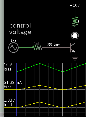
 

I am simply interested to see if this can be done in its simplest form as I explained.

A plain transistor makes current variable through a load, based on what bias voltage you apply.

9763828000_1468720331.png


Notice linear response at bias = 0 to 10V.
 

The current in the variable resistor in an LM317 circuit is only 10mA. How would you accurately control the current in a 20A or 50A Mosfet down so low? The resistance in an LM317 circuit is usually 2k or more but a Mosfet is usually much less than 0.1 ohm.

Use a low current transistor instead of the variable resistor and watch the output voltage from the LM317 increase when heat causes it to turn on more.
 
  • Like
Reactions: Vraj

    Vraj

    Points: 2
    Helpful Answer Positive Rating
I would use simple transistor in place of mosfet transistor.
 

I presume you want a linear control of LM317 output with well defined scaling. This can't work with a simple BJT or MOSFET.

It's possible to superimpose a control voltage or current to the LM317 control pin, e.g. by a resistor or current source. For a specific design, you would decide first about the intended regulator output voltage range. A LED driver is usually designed as a constant current rather than constant voltage regulator, suggesting a different design.
 

If you look hard, you will see that the middle leg is lifted by the bias current. You can select a voltage from the ADC output and feed that to this point.

As FvM has pointed out, the LED brightness cannot be controlled by voltage (well, the IV curve is steep and control is difficult) and is best controlled by current.

You can make a super simple voltage to current converter with 100-900mA output.
 

Hello BradTheRad,

Thanks for replying and thanks for taking the time to answer my thread.

So in your resolution I see you are suggesting a 1 kHz signal to the base of a transistor driving the LED.

Well, that's not the signal I have. The only control signal I have is a 0-10VDc (@20ma max) dac output.

So I don't think your circuit configuration fits my existing circuit criteria. Let me know if we understand each other or if I am making a mistake.

Thanks

- - - Updated - - -

Hello audioguru,


Thank you very much for taking the time to reply.

Yeah okay a simple transistor like a 2n2222 or a 2n3901 is fine with me but is it okay if I put the transistor in parallel with R2 (refer to LM317)?

- - - Updated - - -

Hello vraj,

Thank you so much for replying.

Yes, it seems this is what others recommend. I didn't try it yet.... I will give it a shot in the close future....

Thanks

- - - Updated - - -

Hello fvm and c_mitra,

Thanks guys for replying that is very appreciated.

Ok I am a little confused in the propositions.
Would you guys have a circuit schematic example that would compliment my application.

I was simply thinking to use the LM317 as the LED driver. but I think what you guys are saying is that the LM317 needs to be wired as a constant current configuration in order to control a led. If this is so at:

https://www.ti.com/lit/ds/symlink/lm317.pdf

None of the recommended circuit diagrams take into account for for the LM317 to control a Constantinni current of a LED (~1.5A) while offering a 0-10VDC (coming from a DAC)?

I'm not that good in modifying circuits to obtain the configuration that I would like.

Can you guys provide a sample circuit that would compliment the control signal that I have.

The application is to simply drive and control the luminacity of a led that draws about 1.5A from a dac output that provides 0-10Vdv.

I am willing to even add an offset and do my programming so that I make the dac's out have a one volt offset like for example 1- 10 vdc.

In case I didn't mention to everyone .... The final product is for home LED lighting .....

Thank you so much for taking the time to read this post.
 
Last edited:

I think that Brad's circuit is the one to go for, if you examine it as the input voltage increase to 10V, the base current increases to 52 mA and the collector current increases to 1A. You will need an additional transistor as an emitter follower between the DAC and the base. This will reduce the base current required to about .5 mA. So you need the resistor in series to be about 10V/.5 ~ 20K. There will be a "dead band" of about 1.6V before the collector current starts to increase.
Frank
 

As the transistor heats, its current gain rises which causes its output current to increase. If it is driving the LED through a current-limiting resistor then the LED will get brighter. If there is a resistor from the emitter of the transistor to ground then it provides negative feedback to cancel the heat brightening effect but then the base voltage must be higher than 0.7V.
 

Hi chuckney,

Thanks for replying ?

Ok so you are saying that brads circuit is a good circuit to go with and I thank brad for coming up with it ?.

But I have a question. Brads circuit doesn't even use an LM317.... It's just a transistor that drives a led ???

If this is so then why is everyone using an LM317 to drive high powered LEDs ?

Like for example this video:

https://m.youtube.com/watch?v=y-Txp76rqwE

Thanks everyone
 

So in your resolution I see you are suggesting a 1 kHz signal to the base of a transistor driving the LED.

Well, that's not the signal I have. The only control signal I have is a 0-10VDc (@20ma max) dac output.

My simulation has 1 Hz to create a linear-looking scope trace. However you can apply any frequency of signal, as slow as you wish, or even unchanging DC.

My circuit illustrates a simple way to go (as you requested), but it may not do everything you wish. It may need to have more added to it.

Example, post #8 suggests two transistors, which amplifies the gain from your 20mA control signal.

Post #9 suggests a way to prevent thermal runaway.
 

Ok guys,

Ooops sorry o don't know where I got 1khz??? ?

I will take post 8 and 9 into consideration and will try to make brad's circuit?

Thanks everyone for your collaboration and thanks Brad for your generous reply and contribution to this thread.

I will let you guys know how this pans out ☺️
 

Ref you question about LM317 and LEDs. The LM alters its output voltage in order to keep the error input at 1.2V, so if its stabilising 10V, the the 10V is potted down to 1.2V and fed to the erorr input.
So to use with LEDs, you put a current monitoring resistor in series with the LEDs at the earth end. You arrange the voltage drop across the resistor at the optimum LED current to be 1.2V. You then drive the LEDs from the LM stabilised output. So if the LEDs need 1A, you need a 1.2 ohm resistor.
Frank
 

Status
Not open for further replies.

Part and Inventory Search

Welcome to EDABoard.com

Sponsor

Back
Top