Continue to Site

Welcome to EDAboard.com

Welcome to our site! EDAboard.com is an international Electronics Discussion Forum focused on EDA software, circuits, schematics, books, theory, papers, asic, pld, 8051, DSP, Network, RF, Analog Design, PCB, Service Manuals... and a whole lot more! To participate you need to register. Registration is free. Click here to register now.

Can't run a 24V DC fan with NPN PWM output signal

eagle1109

Full Member level 6
Joined
Nov 20, 2014
Messages
390
Helped
4
Reputation
10
Reaction score
7
Trophy points
1,298
Location
Saudi Arabia
Activity points
5,928
Hello,

I bought this module from Aliexpress to attach it to a Mitsubishi PLC FX3U clone, that can output 0-10V analog DC voltage which isn't effective and enough to run a 24V DC fan. So I bought this module to solve this problem.

The module specs:
1. Power supply voltage 7-30V
2. Control input signal 0-5V or 0-10V can be selected with a jumper
3. 2 output signals: NPN can be 5 or 24V, PNP can only be 5V PWM signal

This is the connection:
vdc_to_pwm_converter_circuit.png


The problem is that the fan only worked on PNP rail and didn't work on NPN.

I wired the output for PNP and NPN the same, the red wire goes to the output path NPN or PNP and the black goes to the one of the two GND pins.


Is there a problem with my NPN wiring ?
 
Hi,

There are a few things you need to check.

For NPN connection:
Fan +ve -> +24V
Fan -ve -> collector
IC pin to source base current during ON time. This means +ve PWM signal.

For PNP connection:
Fan +ve -> collector
Fan -ve -> gnd
IC pin to sink base current during ON time. This means -ve PWM signal.

Looking at the board, it seems like you could switch between jumper positions to select between +ve and -ve PWM signals.
--- Updated ---

Keep feedback coming.
--- Updated ---

Remember to connect a freewheeling diode across the fan.
 
Last edited:
Hi,

You absolutely right Mr Akanimo :)

It worked perfectly.

A surprising factor is that with NPN configuration it worked OFF with Full 10V signal, and ON with 0V !
I remember the NPN work with +ve signal on the base, and PNP with a 0V on the base to be full open.

1. Here's the fan running on full speed, putting 0V on the input control signal.

24V fan PWM driver (1).jpg


2. Running on OFF state, putting 10V on the input control signal.

24V fan PWM driver (2).jpg


3. I tried to catch the kick off voltage to run the fan on the slowest speed, but I couldn't get a relatively slow speed. It kicks off with a moderate speed. It's not important but I thought a module like this one provide this functionality or there might be other factors; like, the frequency or I have to add other auxiliary components.

It kicks off with 9.6-9.7V.

24V fan PWM driver (3).jpg
 
To slow down the speed, you need to reduce the duty cycle of the PWM signal.
 
Most fans like that are brushless and have their own built in oscillator (Hall effect device and current amplifier) so PWM will interfere with its operation. You might be able to convert the PWM to variable DC to get some speed control but pulsing on and off with direct PWM probably won't work.
It would be rather like driving a car with the accelerator hard down and using the ignition key to control the road speed.
Brian.
 
Do you have a schematic or related documentation for the board? We could see why it behaves that way.
--- Updated ---

Another possibility: The fan may have an internal pull-up resistor at the control input terminal. Do you have a datasheet for it?
 
Last edited:
To slow down the speed, you need to reduce the duty cycle of the PWM signal.
I've done that actually, when I send 9.7V to input signal that gives the lowest duty cycle rate.

The small potentiometer is to change the frequency of the PWM, I didn't test that part, I thought frequency doesn't matter.
--- Updated ---

Most fans like that are brushless and have their own built in oscillator (Hall effect device and current amplifier) so PWM will interfere with its operation.

OK, I got it, I remember finding a small PCB attached behind the sticker and has some parts and a small IC. Yep, now I understand that small PCB more.

So the fan isn't just a rotor with coils and magnetic stator, added parts required for smooth and better operation, am I right here ?

You might be able to convert the PWM to variable DC to get some speed control but pulsing on and off with direct PWM probably won't work.
It would be rather like driving a car with the accelerator hard down and using the ignition key to control the road speed.
Brian.
Well, it's a long story. I actually bought this board to connect it to a clone PLC for the Mitsubishi FX3U PLC.

The clone is simulating the main functions of the Mitsubishi FX3U PLC.

This is the original PLC:
1705675758552.png


This is the clone PLC pinout:
fx3u-14mr-1.jpg


So the story, is that, we wanted not to drive the fan as ON/OFF type of operation and wanted to use speed control. So there are analog output pins through DA0-DA1, but they provide from 0-10V only. I didn't think of many ways to solve this problem and thought PWM is the way to go.

So I searched for a part that can convert analog 10V to 24V PWM and found this one perfectly fitting my setup.

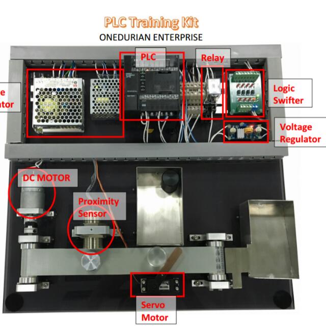
It's a good addition, because the project is for college final year graduation projects showroom. The whole thing would be done on a piece of wood and found the whole project parts on the wooden base; like this:

plc_training_kit_1496974068_88d40246.jpg


or like this:
1705676419090.png

--- Updated ---

Do you have a schematic or related documentation for the board? We could see why it behaves that way.
No, it's found on Amazon and Aliexpress and some other sites, but didn't even find a tutorial or YouTube review about it.

Another possibility: The fan may have an internal pull-up resistor at the control input terminal. Do you have a datasheet for it?
Even the fan, I just bought it from Aliexpress I don't have more information, I might check the sticker next time. I might be from a company that has provided a datasheet for it.
 

Attachments

  • 1705676369629.png
    1705676369629.png
    2 MB · Views: 50
Last edited:
Another possibility: The fan may have an internal pull-up resistor at the control input terminal. Do you have a datasheet for it?
So the output of your board is a PWM signal. So the board converts the DC control voltage to modulated pulse width. From the information you have provided, the pull-up resistor would be on the board rather than in the fan.
 
With a 2 wire fan, I found the best way to make it variable was to control with current using a linear transistor to sink current, so it had to dissipate about 1W into a heatsink at half power. At steady speed, the fan appears like a 2.5W resistor but acceleration takes more current. Meanwhile inside is a closed loop speed control with Hall sensors for sensing and FETs for power switching of each phase. Using PWM causing aliasing effects and I figured it was not so good for its internal capacitors. A thermistor bridge controlled the fan current from 0~100% on a hotspot from 45 to 55'C
 
The small potentiometer is to change the frequency of the PWM, I didn't test that part, I thought frequency doesn't matter.
Could you let us see what the waveform that goes into the fan looks like on a scope?
 
Could you let us see what the waveform that goes into the fan looks like on a scope?

1. NPN signal - 24V:
pwm_signal_24V.jpg


2. PNP signal - 5V:
pwm_signal_5V.jpg

--- Updated ---

The frequency according to the module specs ranges from 2k-20khz.
--- Updated ---

So the output of your board is a PWM signal. So the board converts the DC control voltage to modulated pulse width. From the information you have provided, the pull-up resistor would be on the board rather than in the fan.

Do you mean according to your solution in #2, that the actual transistor driver circuits in this module are done in this way ?

1705693135307.png
 
Last edited:
I seriously don't think it will work as you intended.

Using PWM is fine but the small PCB inside the rotor hub will be very confused if it tries to regulate the speed and you chop the power to it to slow it down.
The trick is to convert the PWM to a DC voltage and then use that DC to control the fan motor current. From the scope traces it looks like the PWM frequency is about 7.2KHz, you need to find the average of the waveform by using the 'on' time to charge a capacitor while the transistor or some other load tries to discharge it. The theory is that changing the on to off ratio will allow the average voltage to be controlled. You can then use that average to feed current to the base of your transistor and hence control its collector current.

The additional components can be quite simple, probably two resistors in series and a capacitor from their junction to ground. The feed side resistor limits the charge to the capacitor and the load side is to limit the current to the transistor base. Look on line for the calculations needed to find the values, there is a trade off of ripple in the voltage versus response time which you will have to find for yourself but consider that the mass of the fan blades means their speed will be slow to change anyway.

Brian.
 
Buy a fan with the 3rd wire for PWM control.

if you are going to use your ckt - add the free wheeling diode and an LC filter ckt to turn it into a proper buck ckt - the fan will thank you for it !
 
I seriously don't think it will work as you intended.

Using PWM is fine but the small PCB inside the rotor hub will be very confused if it tries to regulate the speed and you chop the power to it to slow it down.
The trick is to convert the PWM to a DC voltage and then use that DC to control the fan motor current.

Yeah, I understand the point. So it's not meant to be run by a PWM signal.

I've actually dealt with fans with a 3rd wire which I know it's meant to be controlled by a PWM signal, and knew that there're fans with 2 wires and I think I have a little idea that they meant to be run with direct voltage either full run speed or zero speed but now I understand the idea more clearly.

If; for example, there is a DC motor with 2 wires but with no other parts like the small PCB attached with this fan, then I think it's OK to run it with a PWM signal, but in the fan's case, it's not suitable.

It's OK, I just have to find another solution and I'm happy that I'm learning new thing now about fans.

I'm thinking either I design a transistor driver circuit with the required parts and do some experiments on the fan.

From the scope traces it looks like the PWM frequency is about 7.2KHz, you need to find the average of the waveform by using the 'on' time to charge a capacitor while the transistor or some other load tries to discharge it. The theory is that changing the on to off ratio will allow the average voltage to be controlled. You can then use that average to feed current to the base of your transistor and hence control its collector current.

Do you mean here by this solution, in case if I wanted to continue using this module to drive the fan ? If that's what you mean, then I'm actually changed my mind as soon you told me about the little PCB and a PWM signal is not the goal in this case.

But the I think the method you described here is like the smoothing process done in SMPS with the chopped voltage after the HFT using capacitors, am I right ?

The additional components can be quite simple, probably two resistors in series and a capacitor from their junction to ground. The feed side resistor limits the charge to the capacitor and the load side is to limit the current to the transistor base. Look on line for the calculations needed to find the values, there is a trade off of ripple in the voltage versus response time which you will have to find for yourself but consider that the mass of the fan blades means their speed will be slow to change anyway.

In this case, I'm thinking of canceling this module, and just get the variable 0-10V from the PLC to a transistor driver circuit, I have to search for a good circuit design online.
--- Updated ---

Buy a fan with the 3rd wire for PWM control.
Yep, I either have to buy a fan with 3 wires, or buy/design a transistor circuit driver to control the current going to the fan.

if you are going to use your ckt - add the free wheeling diode and an LC filter ckt to turn it into a proper buck ckt - the fan will thank you for it !
Do you mean the LC filter for the diode ?
 
Last edited:
But the I think the method you described here is like the smoothing process done in SMPS with the chopped voltage after the HFT using capacitors, am I right ?
Similar but not quite the same. In your fan control, the only way you can change the speed is to vary the DC voltage across it. Chopping the voltage off and on repeatedly with PWM will not work, at least as you expect. So what you have to do is convert the PWM to DC. It is a simple task, especially as the resulting DC doesn't have to be very 'clean' because the fan will tolerate noise and ripple on its supply.

There is a simple tutorial here: https://www.instructables.com/Arduino-RC-Circuit-PWM-to-analog-DC/
It takes PWM from an Arduino board but the same principle applies with PWM from your controller.

Basically, if the PWM is always low, the average is zero so no voltage is produced, if it is always high the average is full voltage. At 50:50 PWM the average is one half of full voltage, at 25% on, 75% off it will be on quarter of full voltage. Whatever the PWM duty cycle, you get that same proportion of full voltage produced.

Brian.
 
Do you mean according to your solution in #2, that the actual transistor driver circuits in this module are done in this way ?

View attachment 188034
So this would not work because of the type of device that you are driving, unless you are going to run it at 0% duty cycle (for OFF), 100% duty cycle (for ON) and nothing inbetween. If you need to vary the speed, then you may have to change the device to a different type.
 
Last edited:
" Do you mean the LC filter for the diode ? "

look up buck converter on the net - you have almost built one . . .
 
Similar but not quite the same. In your fan control, the only way you can change the speed is to vary the DC voltage across it. Chopping the voltage off and on repeatedly with PWM will not work, at least as you expect. So what you have to do is convert the PWM to DC. It is a simple task, especially as the resulting DC doesn't have to be very 'clean' because the fan will tolerate noise and ripple on its supply.

There is a simple tutorial here: https://www.instructables.com/Arduino-RC-Circuit-PWM-to-analog-DC/
It takes PWM from an Arduino board but the same principle applies with PWM from your controller.

Basically, if the PWM is always low, the average is zero so no voltage is produced, if it is always high the average is full voltage. At 50:50 PWM the average is one half of full voltage, at 25% on, 75% off it will be on quarter of full voltage. Whatever the PWM duty cycle, you get that same proportion of full voltage produced.

Brian.

Yeah, I understand that, I just thought that PWM is the solution in my case, didn't know about the little PCB, I know there's one but didn't know it would interfere with the coming PWM signal.

And since the PLC actually can produce variable voltage on DA0 which is a DAC output pin I believe. So in this case, I just have to remove the DC/PWM converter module from the project. And according to this diagram, I have 2 options:

fan_run_options.png


Of course option#2 won't work, even if the max output voltage will not have the required current to move the fan.

So, how about using the DAC output to driver a MOSFET and then driver the fan ?

fan_mosfet_driver.png
 
Yeah, I understand that, I just thought that PWM is the solution in my case, didn't know about the little PCB, I know there's one but didn't know it would interfere with the coming PWM signal.

And since the PLC actually can produce variable voltage on DA0 which is a DAC output pin I believe. So in this case, I just have to remove the DC/PWM converter module from the project. And according to this diagram, I have 2 options:

View attachment 188094

Of course option#2 won't work, even if the max output voltage will not have the required current to move the fan.

So, how about using the DAC output to driver a MOSFET and then driver the fan ?

View attachment 188099
The fan may be internally controlled at a fixed speed irrespective of the input DC voltage. So, first of all, you need to check whether the speed of the fan depends on the input DC voltage. You can take like 4 or 5 equally-spaced points along the DC voltage range to check whether the speed of the fan varies with input DC voltage or not.
 

LaTeX Commands Quick-Menu:

Part and Inventory Search

Welcome to EDABoard.com

Sponsor

Back
Top