Continue to Site

Welcome to EDAboard.com

Welcome to our site! EDAboard.com is an international Electronics Discussion Forum focused on EDA software, circuits, schematics, books, theory, papers, asic, pld, 8051, DSP, Network, RF, Analog Design, PCB, Service Manuals... and a whole lot more! To participate you need to register. Registration is free. Click here to register now.

[SOLVED] Driving a series RLC circuit with a square wave.

Status
Not open for further replies.

engrMunna

Advanced Member level 4
Joined
Oct 25, 2010
Messages
106
Helped
6
Reputation
12
Reaction score
5
Trophy points
1,298
Activity points
2,071
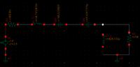
I am drving a series RLC circuit (see picture) with a square wave which has the same fundamental frequency as that of the resonance frequency of the RLC circuit. I have place a 600 miliOhm (0.6 Ohm) resistance in front of the source (just for the sake of the simulation). Now across the 50 ohm resistor I get a sine wave, which I should as this is a bandpass filter.

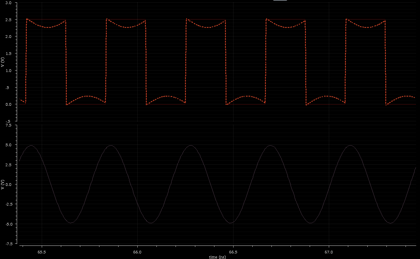
But my question is about the waveform at the node in between the 0.6 Ohm resistance and L112 (48.7nH). Here according to my undersanding I shold have a square wave but what I get is a square wave with some curves at the top of it pulse...if you see the picture you'll get what I mean by curve.

In the wavefrom picture, the dotted line is the voltage at the node i mentioned, and you can see the curve in the voltage waveform as compared to the voltage of the source.
At the bottom is the sine wave i get across the 50 ohm resistance.

So why does the voltage waveform have a curve at the node in between R3 and L112?????


There must be a voltage drop according to the filter input current...

Hmm yes you are right because if we do the maths it says "almost" the same (but since this is an ideal setup it should be exact and not almost..will verify with accurate numbers tommorrow).
Any way about the math... the sine voltage is across the 50 ohm load and with a peak value of 5V so a current of 5/50 = 0.1A is flowing and at resonance we are left only with the the two resistor in series. So this mean a peak voltage drop of 0.1A * 0.6ohm = 0.06V across R3. and 2.5V - 0.06V = 2.44V..and in the graph we can see the voltage drops to about 2.3V which is close to 2.44V....let me confirm with exact numbers tomorrow...because I think at resonance there was a very small hint of capacitance in the impednace looking into the filter.

Thanks FvM for providing this insight!
 

Any way about the math... the sine voltage is across the 50 ohm load and with a peak value of 5V so a current of 5/50 = 0.1A is flowing and at resonance we are left only with the the two resistor in series.
Definitely not right. If you remove the 50 ohm resistor, the series LC circuit shorts the input source in resonance. The 50 ohm resistance gets transformed to a very low resistance according to the characteristic impedance of the resonator.

It should be mentioned, that the resonator impedance is several orders of magnitude off from values that can be implemented in a real 2.4 GHz circuit. So all calculations are more or less void, just playing with RLC values in a simulator.

In other words, you need to learn about the "reality factor" in RF design. As a starting point, you should assume circuit impedances that aren't more than factor 10 above or below 50 ohms.
 
FvM I am not clear about your answer. What is not right? Yes i have chosen the LC values such that the 50 Ohm gets trasnformed to a 2.5ohm resistance when seen by the source at resonance.

What I meant to say is that at resonance the imgainary part is canceled and we see a 2.5 ohm resisance lookin into the RLC network.
Also why are the resonator impedance off from values that can be implemented at 2.4GhZ? can you explain this more?

-------------------------------

Ok So I did nad the numbers match exactly.....and the distortion in the square wave after the 0.6ohm R3 is because the RLC filter draws a sinosoidal shaped from the square wave and this causes the drop across R3 to make the square wave distorted.

although problem solved...but I am still confused about FvMs' last comments
 
Last edited:

although problem solved...but I am still confused about FvMs' last comments
Your previous post claimed that the resonance case can be simplified to two resistors (0.6 and 50 ohm) in series. It's correct that the imaginary part cancels in resonance, but as you already found out,the transformed resistance is not 50 ohm.

The more important point was about which inductor and capacitor values that can be implemented in a real circuit. It still holds.
 
Status
Not open for further replies.

Similar threads

Part and Inventory Search

Welcome to EDABoard.com

Sponsor

Back
Top