Continue to Site

Welcome to EDAboard.com

Welcome to our site! EDAboard.com is an international Electronics Discussion Forum focused on EDA software, circuits, schematics, books, theory, papers, asic, pld, 8051, DSP, Network, RF, Analog Design, PCB, Service Manuals... and a whole lot more! To participate you need to register. Registration is free. Click here to register now.

Digital Clock Manager Reset

Status
Not open for further replies.

FecP

Newbie level 6
Joined
Oct 17, 2016
Messages
14
Helped
0
Reputation
0
Reaction score
0
Trophy points
1
Activity points
160
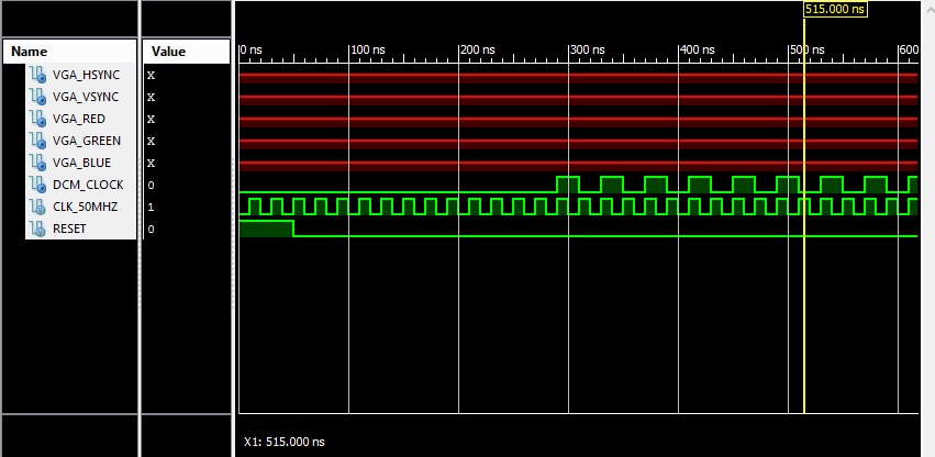
The input clock is at 50 Mhz and I need the output (clk) at 25 Mhz.


Code Verilog - [expand]
1
2
3
4
5
6
7
8
9
10
11
12
13
14
15
16
17
18
19
20
21
22
23
24
25
26
27
28
29
30
31
32
33
34
35
36
DigitalClockManager instance_name (
    .CLKIN_IN(CLK_50MHZ), 
    .RST_IN(rst_in), 
    .CLKFX_OUT(clk), 
    .CLKIN_IBUFG_OUT(CLKIN_IBUFG_OUT), 
    .CLK0_OUT(), 
    .LOCKED_OUT(LOCKED)
    );   
     
BUFG buffer (.I(CLKIN_IBUFG_OUT), .O(CLKIN)); 
 
 
always @ (posedge CLKIN)
    begin
        if(RESET)
            begin
                enable <= 0;
                SR[0]  <= 0;
            end
        else 
            begin
                enable <= enable + 1;
                if(!LOCKED && !enable)
                    SR[0] <= 1;
                else 
                    SR[0] <= 0;
            end
    end
 
 
always @ (posedge CLKIN)
    begin
        SR <= SR >> 1;
    end
 
assign rst_in    = (SR[2] | SR[1] | SR[0]);    //assert reset for 3 clock cyles


If the clocked output isn't "LOCKED" , should a new reset signal be sent every clock cycle? I've used the enable counter to provide a delay between successive reset pulses i.e(give clock manager time to lock)? And a shift register to make the rst_in to last 3 seconds.
P.S. Is this the right way to reset a DCM? Wouldn't it be better if I tied the DCM 'rst_in' to the external reset? assign rst_in = RESET (From FPGA button)?


Have you read UG382, namely the sections titled "Using the LOCKED Signal" and "RST Input Behavior"?

In summary you should reset when there is a high->low transition on LOCKED and when either of the non-sticky status[2] or status[0] bits get set (means the clocks stopped).

Your "enable" bothers me as it looks like a potential dead lock condition as it could force a new reset (with a start of a new lock acquire) if the DCM is slow to lock on the clock (maybe the clock has excessive jitter.

I also have an issue with using the logical ! (not) operator on a bus (!enable). The logical operators are defined for use on single bits not buses. Using the correct reduction NOR operation is preferred for detection a bus is 0, i.e. ~|enable. This lets another reader of your code understand the intent better.

I also don't understand how this is supposed to result in 3 clocks of SR...
Code:
SR[0] <= 1;
SR <= SR >> 1;
assign rst_in    = (SR[2] | SR[1] | SR[0]);    //assert reset for 3 clock cyles
How is a right shift supposed to do anything SR[2:1] are never 1. You could have also used a reduction OR instead of writing out all the bits.
Code:
assign rst_in = |SR;

Your code may also result in multiple drivers when compiling it as SR is driven by two different always blocks. I always avoid this type of coding style as it may give different results depending on the tool.
 
  • Like
Reactions: FecP

    FecP

    Points: 2
    Helpful Answer Positive Rating
Thank you for your comprehensive answer! I am a beginner and the coding guidelines are really helpful.

I should have mentioned that I am using a Spartan 3-E board and it says in the data sheet regarding Spartan 3-E that :

This function is not supported in the Spartan-3E family.
In the Spartan-3 family, STATUS[0] also indicates overflow for a
fixed phase shift selection

And it says that STATUS[1] bit checks for CLKIN stability, so should I use STATUS[1] instead?


Code:
        reg [2 : 0] SR;
	reg LOCKED_R;
	
	always @ (posedge CLKIN)
begin
	if(RESET)                            //EXTERNAL SYNC. RESET
	SR  <= 1;
	else 
	begin
	LOCKED_R <= LOCKED;
	SR <= SR >> 1;
	if(LOCKED < LOCKED_R || STATUS[2] || STATUS [0] ) // H to L
	SR[2] <= 1;
	else 
	SR[2] <= 0;
	end
end


assign rst_in    = ( (SR[2] | SR[1] | SR[0]) || RESET);

Code:
	 DigitalClockManager instance_name (
    .CLKIN_IN(CLK_50MHZ), 
    .RST_IN(rst_in), 
    .CLKFX_OUT(clk), 
    .CLKIN_IBUFG_OUT(CLKIN_IBUFG_OUT), 
    .CLK0_OUT(), 
    .LOCKED_OUT(LOCKED), 
    .STATUS_OUT(STATUS)
    );
	 
	BUFG buffer (.I(CLKIN_IBUFG_OUT), .O(CLKIN));

Would this work? SR is supposed to be a 3 bit shift register that provides a 3 clock cycles long reset the data sheet mandates.
 

Code:
	reg LOCKED_R;
	reg [3 : 0] SR;	
	always @ (posedge CLKIN)
begin
	if(RESET)
	begin
	SR [3 : 0]  <= 4'b111;
	LOCKED_R <=0;
	end

	else 
	begin
	LOCKED_R <= LOCKED;
	if(LOCKED < LOCKED_R | STATUS [1] ) // H to L on LOCKED | CLKIN UNSTABLE
	SR <= {1'b1 , SR[3 : 1]};
	else 
	SR <= {1'b0 , SR[3 : 1]};
	end
end

assign rst_in    = ( (SR[2] | SR[1] | SR[0]) || RESET);

Now, I am not sure about how to implement reset for all the other registers in the design, since they are driven by the DCM clock output.
If the RESET signal pulse lasts for a period shorter than what it takes to assert the locked signal, (which probably will be the case because of the OR gate at the rst_in), the registers will never be reset.


Code:
always @ (posedge clk) 
begin  
   if (LOCKED && !STATUS[1])
	begin 
           //GOOD TO GO
	end
	else

	begin
	 //RESET
	end
end


Does the always @ (posedge clk) trigger even when (LOCKED && !STATUS[1]) isn't high? If so, why does the simulation show everything inactive until the locked bit doesn't go high?
Will I have to use an async RESET to reset my registers?


Status
Not open for further replies.

Part and Inventory Search

Welcome to EDABoard.com

Sponsor

Back
Top