Continue to Site

Welcome to EDAboard.com

Welcome to our site! EDAboard.com is an international Electronics Discussion Forum focused on EDA software, circuits, schematics, books, theory, papers, asic, pld, 8051, DSP, Network, RF, Analog Design, PCB, Service Manuals... and a whole lot more! To participate you need to register. Registration is free. Click here to register now.

Diff Amp circuit issue

Status
Not open for further replies.

ringo888

Member level 1
Joined
Feb 2, 2009
Messages
39
Helped
0
Reputation
0
Reaction score
0
Trophy points
1,286
Activity points
1,577
Hi Guys,

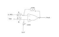
I have a differential amplifier circuit with a voltage input range of 2.95-3.00V and I wanted to expand the range by using the differential amp with 2.5V on the +ve input of the amp and using a gain of 10 to give me a range of 0.9V to 5V at 0.1V steps.

The issue I have is that when i simulate the circuit the output voltage is going down and after 2.7V it goes to 0V (btw the amp is common mode, no negative). So my question is why is this happening and how to i resolve this. I was using the equation (V1-V2)*(Rf/Rg).

Any help would be appreciated, i've attached a jpg of my circuit.

Thanks Ringo
 

Attachments

  • DIFF AMP.jpg
    DIFF AMP.jpg
    52.5 KB · Views: 73

V1 = 2.5V (Vin+) and V2 = 2.59 (Vin-) which ok would give me -0.09V*10 = -0.9V but my sim is giving 1.6V??

Is my circuit correct or have i missed anything out?
 

VOUT-VREF=-10(VIN-VREF)
The simulation is correct.

Added : Your diagram is showing a gain of -20 and not -10.
 

Oh sorry theres another 10K on the input Vin- else where on the circuit.

My tutor has said that the output would be inverted which is whats happening, as you increase int input voltage on V2 2.59V-3.00V the value decreases, but i don't understand why?
 

You have to know how to derive the equation, instead of plucking equations from textbooks or blindly listening to your tutor.
Go back to basics and derive the equation.
If you want to use the standard-form equation, you can see it as the "gnd" reference is now "ref". That implies that both your input and output is now referenced to "ref" instead of "gnd".

Added : You do know that this is an inverting amp right?
 

Sorry, CHECKMATE, you are not correct.

The output voltage is: Vout=2.5*(1+20)-2.59*20=-1.8 volts.
Consequence: cannot work with single (positive) supply.

Ringo, what about the resistor "elsewhere on the circuit" ???
 

Yes i know its inverting but i thought thats the only way you can design differential amps, are you saying you can swap the inputs round?
 

Sorry, CHECKMATE, you are not correct.

The output voltage is: Vout=2.5*(1+20)-2.59*20=-1.8 volts.
Consequence: cannot work with single (positive) supply.

Ringo, what about the resistor "elsewhere on the circuit" ???
Hi LvW, my equation is correct. It is also proven by ringo's simulation.

---------- Post added at 15:45 ---------- Previous post was at 15:42 ----------

Yes i know its inverting but i thought thats the only way you can design differential amps, are you saying you can swap the inputs round?

Are you looking for a difference amplifier? Then you have the wrong circuit.
Operational amplifier applications - Wikipedia, the free encyclopedia
 
LvW, that sounds more like what i'm seeing!!

ahh right i see, so what would you recommend if i wanted to increase the resolution of a voltage range between 2.59v-3V and expand out to 0-5V.

Its actually a 10K resistor to a RTD but i'm not simulating that and just have 20k on Rg

So where did the (1+20) come from? Is the "1" due to it being single supply?
 

CHECKMATE, sorry; I have overlooked the term Vref on the left side of your equation.
Rather I have expected the classical form Vout=1+....

RINGO8888, the voltage Vref (2.5 volts) is multiplied with a factor that resembles the classical non-inverting gain formula
Vout=(1+R2/R1) with R2/R1=200/10.
 
Guys thanks very much, i'm still lost as i can caluculate both -0.9V from Checkmates equation (and on wiki) and 1.8V on LvW's

Can I use a diff amp with the inputs inverted, i.e. with the input wires on my diagram the other way around
 

I have calculated with Rg=10 kohms as shown in your diagram.
No, you cannot change the inputs since you always need negative feedback.
Perhaps it would be a good idea to correct your scetch if necessary (and not confuse us with an additional rersistor "elsewhere")
 

Ok i've attached an update, i think i've confused things by refering to Rg so i've added designators, R3 is the only difference and is now 20k
 

Attachments

  • diff amp2.jpg
    diff amp2.jpg
    50.7 KB · Views: 74

Thanks for clarification.
With Rg=20k the inverting gain is -10 (non-inv. +11) and therefore:

Vout=Vin*(-10)+Vref*(+11)=+27.5 V - 10*Vin.
With numbers: (27.5-25.9=+1.6 V) ......(27.5-30=-2.5V) >>>>> output swings from +1.6 to -2.5 volts.
That means, you need split supply, otherwise your output cannot swing pos. and negative.
 

You just want to translate (2.95~3)V to (0~5)V right?
The transfer function is then

Vout-2.5=100(Vin-2.975)
=100(Vin-2.5)-100(2.975-2.5)


If you are going to generate the 2.975V and 2.5V from a resistor tree, you are going to need to buffer them.
 

    V

    Points: 2
    Helpful Answer Positive Rating
another way to write this is Vout = VR + ((RF/R1)*(V2-V1))

53358d1297830170-diffamp-jpg


Alex
 

    V

    Points: 2
    Helpful Answer Positive Rating
Status
Not open for further replies.

Similar threads

Part and Inventory Search

Welcome to EDABoard.com

Sponsor

Back
Top