Continue to Site

Welcome to EDAboard.com

Welcome to our site! EDAboard.com is an international Electronics Discussion Forum focused on EDA software, circuits, schematics, books, theory, papers, asic, pld, 8051, DSP, Network, RF, Analog Design, PCB, Service Manuals... and a whole lot more! To participate you need to register. Registration is free. Click here to register now.

designing switching supply, variable 15-0-15, fixed +5V +3.3V

Status
Not open for further replies.
Hi,

Vfd is the forward voltage drop of the diode at given current. Find in the diode datasheet
Rdc is the dc winding resistance of the inductor. Find in the inductor datasheet
Rhs is the max. On resistance of the fet. Internal fet: find in the switcher datasheet. External fet: Find in the fet datasheet.

If you only need an estimation (or don't have the data by hand) of the values, then you can use these (three) values from the example in the application note. The results will be very near to the true results...

I know it's a hard way to go... especially at the beginning.
But next time everything seems much easier.

Good luck
Klaus
 

Calculations keep giving huge (or too small) numbers, although the input data seems to be correct. Moreover, the inverting application note keeps talking about fixed voltage output, while I need variable output; it screws up things when it comes to which data to use when it refers to minimum and maximum duty cycle, output current and other things... You know what, I'll just switch back to linear regulators, at least there is almost nothing to calculate and it simply works.

Thank you anyway for your help!
 

Okay, so there is still the charge-pump method for obtaining a negative voltage from a positive supply.

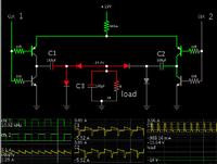
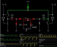
Simulation of not one, but two interleaved charge pumps.
The benefits are the ability to handle greater load, and a smoother waveform is draw from your 19V supply.

Output voltage is subject to parasitic resistances and diode drops.


You can adjust output voltage by altering the duty cycle. Or, use conventional linear regulation.
 

Thanks Brad, but let me get it right: this one is not using a switching regulator at all? I have never seen it before...
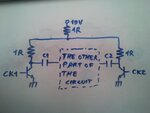
About the NOT gates, may I use a simple transistor NOT gate like in the image below?
IMG_20140605_190952.jpg

Can you provide more info on the other components as well? If I was to re-use the same circuit for creating the positive 15V output, what are the changes to do?

EDIT
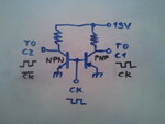
If I can use the NOT gates as above, may I use this method for supplying two inverted clocks on C1 and C2?
IMG_20140605_195332.jpg
 
Last edited:

Thanks Brad, but let me get it right: this one is not using a switching regulator at all? I have never seen it before...

It is based on the handy 'trick' for obtaining a negative voltage from a positive supply.

These simple charge-pumps do not have an easy and efficient way to vary the output voltage. So they tend to get left on the shelf.

About the NOT gates, may I use a simple transistor NOT gate like in the image below?

The half-bridge (two transistors) is needed to allow maximum current back and forth through the charge pump. If you use resistors, then you will get reduced output voltage/current.

I added a resistor inline with the supply: (a) to factor in the effect of parasitic resistance, and (b) because we do not want to draw more than a few A from the 19V supply. The resistor is not needed in a real circuit.

Here is a simulation using transistors. (I increased load to 2A.)


Can you provide more info on the other components as well?

The capacitors can be electrolytics. They acquire a DC charge.

The components carry spikes of several amperes. They should be rated accordingly.

If I was to re-use the same circuit for creating the positive 15V output, what are the changes to do?

Since you already have +19V, you do not need an extra circuit to convert it to +15V. An adjustable regulator will be all you need.

If I can use the NOT gates as above, may I use this method for supplying two inverted clocks on C1 and C2?
View attachment 106043

Yes. (Although did you know your PNP symbol is upside-down?)

For the supply you should the 19V which supplies the charge pump.
 

Status
Not open for further replies.

Similar threads

Part and Inventory Search

Welcome to EDABoard.com

Sponsor

Back
Top