Continue to Site

Welcome to EDAboard.com

Welcome to our site! EDAboard.com is an international Electronics Discussion Forum focused on EDA software, circuits, schematics, books, theory, papers, asic, pld, 8051, DSP, Network, RF, Analog Design, PCB, Service Manuals... and a whole lot more! To participate you need to register. Registration is free. Click here to register now.

Designing low level AM Transmitter on my own first time in life.

Status
Not open for further replies.

Eshal

Advanced Member level 1
Joined
Aug 29, 2012
Messages
470
Helped
16
Reputation
32
Reaction score
15
Trophy points
1,298
Location
Nowhere :)
Activity points
5,149
Hi!

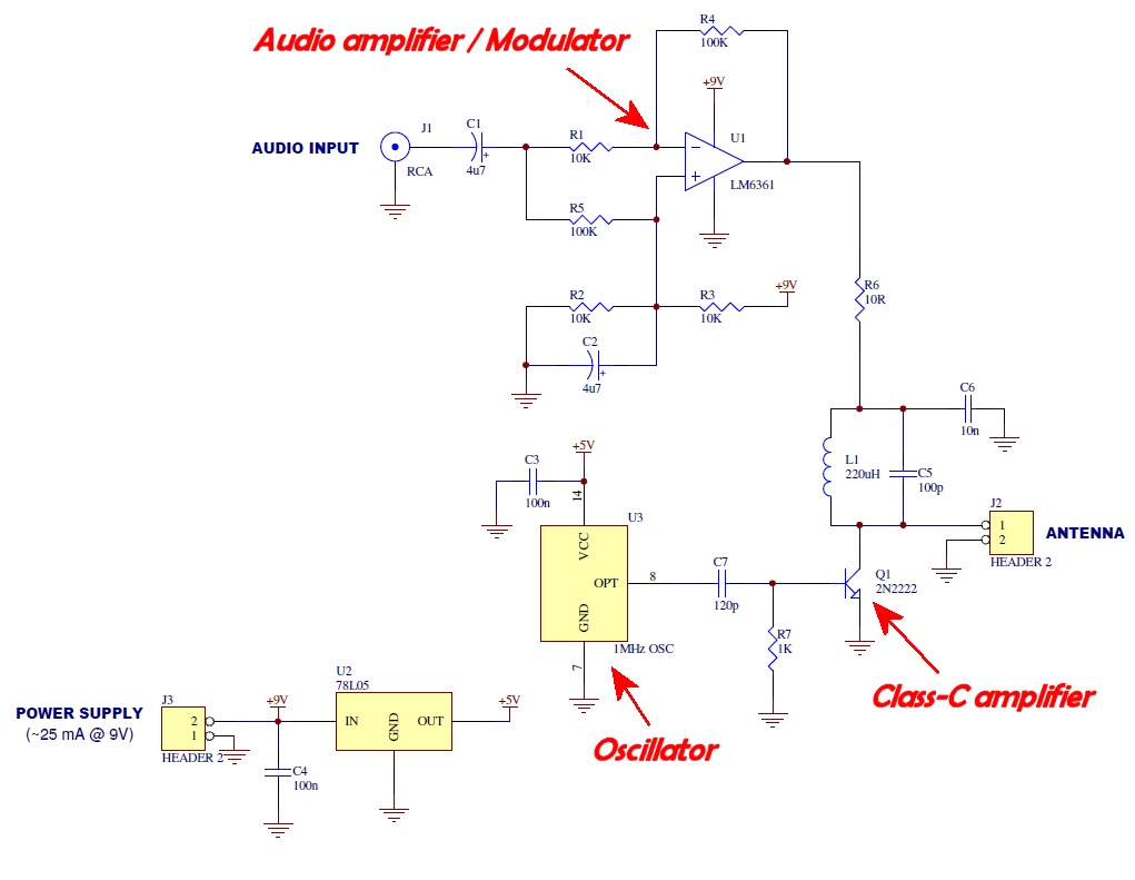
I thought to design low level AM transmitter on my own. This is what I am doing first time in my life. I have some question and need your help guys and gals.

Q) What should be main sections in order to design low level AM transmitter?
Can my transmitter be consist of oscillator section, modulator section and RF amplifier section, is it OK?

Q) For low level, how much DC supply should I use?
9volts are OK for this or not?

Q) Where should I start my designing?
Should I design oscillator first or start from antenna?

Regards,
Cute Princess :)
 

Oscillator, buffer, power amplifier + audio stages - preamp, voltage amp, modulation amp. This for a Class C PA. For a linear RF amp (class A or B) you can modulate a lower level stage, so :- oscillator, buffer, modulation stage, power amp,. Audio stages :- pre-amp, voltage amp.
9V is OK for low power - up tp 1 watt?
Oscillator then towards the AE, remembering what power you need, and your modulation choice. This will give you the correct driver for your next stage
Frank
 

First tell us what frequency you want it to transmit on, this has a big influence on the best design technique. Also tell us what you want to modulate with, is it audio, video or data.

What Chuckey is trying to tell you is to get good AM you must start with a good oscillator. The oscillator type will depend on the frequency you have chosen.
Ideally, the frequency should be very stable and oscillators tend to shift frequency as the load on them changes, this is why a buffer stage was mentioned. It's just a low gain amplifier, primarily there to isolate the modulator so it doesn't effect the oscillator. After that you have the modulator stage, this is the part that controls the 'A' in 'AM', it makes the buffered oscillator signal level vary with whatever you are using to control it. Finally, you have the power amplifier stage which makes the signal powerful enough to drive the antenna.

Please note that there are many AM transmitter designs on the Internet which give extremely poor performance and in some cases can produce harmful interference. In particular, avoid any "one transistor" designs as they are notoriously bad!

Brian.
 

Hiya Eshal,

To add some background to the good advice of Chuckey & betwixt, there are two main approaches to generating AM:
1. Generate the AM signal at a low level (power/amplitude), and boost it to the required output power via linear RF amplification, or
2. Generate the AM at the final power level by directly modulating the gain/amplitude of the final (Class-C i.e. non-linear) RF power amplifier.

There are pros and cons of both approaches and which technique you choose will be influenced by the required power levels, frequency response, audio fidelity and the devices to hand. By way of illustration, here's a simple AM audio transmitter I cobbled together using an ancient 1 MHz TTL oscillator (which consumes the bulk of the operating current shown!) as the frequency determining element. (I've used the second approach to AM modulation in this circuit - also known as "plate modulation" from the old valve transmitter technique of modulating the anode [plate] voltage of the output amplifier).


Have fun experimenting :)
 
Last edited:
Wait.. What you guys are talking about, I am just getting little. Don't you boys know how to teach any girl at her first experiment? Don't you know how to teach a child?

Kindly tell me how to make most simplest AM voice transmitter? The most simple one.

Try to understand what I am asking for. You guys talking much high level conversation.
 

Kindly tell me how to make most simplest AM voice transmitter? The most simple one.
Find somehow a ARRL Handbook (it's available at their site with a reasonable price) search in it and find a AM transmitter circuit diagram and implement it..
 

No. I want to design on my own but the most simplest one however it could transmit over a few range. So you can you guys help me or not?
 

You still haven't told us what frequency you want to use. AM is a kind of transmission, not a band or channel, it can be on any frequency but the design has to be quite different for each one.
Am I right in thinking you want something to transmit your voice so it can be heard on a nearby domestic radio? If so, the frequency should be somewhere between 0.5MHz and 1.5MHz.

Brian.
 

No. I want to design on my own .....

It's quite obvious from your response to the various correspondence that you don't want to design your own, and that you are incapable of doing so. What you do want is for someone to give you a design which you can copy.

You have neither the knowledge or facilities to check whether or not your proposed device caused interference, and I suspect that you don't care.

You should abandon it until you have a lot more knowledge.
 

Eshal said:
So you can you guys help me or not?
I'll give you the benefit of the doubt and say "Most probably" :)

Eshal said:
You guys talking much high level conversation.
That's one of the challenges to responding to a single post requesting information/advice in this forum - there is a very wide range of skills & ability represented amongst our members (not to mention the multiple cultures & languages too) and correctly pitching the level of a response can be difficult. We (incorrectly?) assumed you had a grasp of the required background/fundamentals since you initially asked for help in *designing* a transmitter, as opposed to simply *making* one (which you indicate you actually want to do as per your last post).

The nice thing is this forum caters to people at both ends of the spectrum (the designers and the constructors) and there is no judgement about which type of activity you prefer. Many of us - me included - exist at both ends! All we ask is that you don't get offended/defensive when someone assumes something about your ability from a few scant words. We're all here *voluntarily* to help. Rephrase your question, and ask again... nicely.

OK, with that out of the way, what - exactly - are you wanting to do? Broadcast your voice across the room? Build a college/community radio station? What power/frequency?
Do you want help in *designing* (which will require you to be comfortable with the RF behaviour of transistors) your circuit, or do you want us to recommend an easy-to-assemble design and explain to you [at some level] how it works?

And to help us help you further - what is your level of experience with electronics? There's nothing wrong with the answer being "just starting out", but be aware that radio circuits are generally more ambitious than other types of projects you could get started with.
 
@betwixt
You still haven't told us what frequency you want to use. AM is a kind of transmission, not a band or channel, it can be on any frequency but the design has to be quite different for each one.
I don't know how much frequency is required. I just know I want to transmit my voice over a few range in feet or meters.
Am I right in thinking you want something to transmit your voice so it can be heard on a nearby domestic radio? If so, the frequency should be somewhere between 0.5MHz and 1.5MHz.
Yes dear you are right, I want to transmit my voice so that it can heard on a nearby domestic radio.

You are the one betwixt, who could understood still what I am trying to say. Thanks for this. Help me further.

- - - Updated - - -

@ syncopator
It's quite obvious from your response to the various correspondence that you don't want to design your own, and that you are incapable of doing so. What you do want is for someone to give you a design which you can copy.

You have neither the knowledge or facilities to check whether or not your proposed device caused interference, and I suspect that you don't care.

You should abandon it until you have a lot more knowledge.
Actually, what I got knowledge is all about from book, I am using electronic communication modulation and transmission by Robert J. Schoenbeck. And in this book he didn't mention anywhere how much frequency is required to transmit voice, neither I have any help to do this that's why I turn to this forum but you guys seem not to help me. :-(

- - - Updated - - -

@thylacine1975
I'll give you the benefit of the doubt and say "Most probably" :)
Thank you mister :)
That's one of the challenges to responding to a single post requesting information/advice in this forum - there is a very wide range of skills & ability represented amongst our members (not to mention the multiple cultures & languages too) and correctly pitching the level of a response can be difficult. We (incorrectly?) assumed you had a grasp of the required background/fundamentals since you initially asked for help in *designing* a transmitter, as opposed to simply *making* one (which you indicate you actually want to do as per your last post).
But I am newly adopted girl to electronics heheheheh.. lol :-D
I know what parts are required to make transmitters or receivers. I also know what calculations are needed but don't know how much frequency is needed for what. I want to transmit my voice but don't know how much frequency I required and similarly don't know what should be the oscillator frequency and what should be the DC supply voltage for transmitter. :-(
The nice thing is this forum caters to people at both ends of the spectrum (the designers and the constructors) and there is no judgement about which type of activity you prefer. Many of us - me included - exist at both ends! All we ask is that you don't get offended/defensive when someone assumes something about your ability from a few scant words. We're all here *voluntarily* to help. Rephrase your question, and ask again... nicely.
Thanks for you voluntarily help but please don't ask me to repost my question or I will loose the starting of the thread which I have gotten now. :)
OK, with that out of the way, what - exactly - are you wanting to do? Broadcast your voice across the room? Build a college/community radio station? What power/frequency?
Do you want help in *designing* (which will require you to be comfortable with the RF behaviour of transistors) your circuit, or do you want us to recommend an easy-to-assemble design and explain to you [at some level] how it works?
I want to transmit my voice over low range.
Yes, want to broadcast my voice across the room.
I never build any college or community radio station.
I don't know what power and frequency is required in order to transmit voice over a few range say, 30 feet.
I know behaviour of transistor and don't teach me any pre-assembled circuit. Just help me in designing with lowest level, think you are teaching a girl how to walk by holding her finger in your hand and I assure you I will soon learn walking. But be sincere.

Thank you all you. Especially betwixt and thylacine1975
 

OK, I'll be honest and say despite our/your best efforts/intentions, we're not going to be able to teach you all the necessary background in an internet forum - there is simply too much diverse ground to cover. (This is why an engineering degree takes years). What we can do though, is give you some pointers and leave you to experiment. There is no better teacher than your own time and enthusiasm to chase down something that interests you!

So, to answer some questions:

As betwixt said, if you want to use a domestic AM radio as your receiver, your transmitter will need to use a frequency a) unused by any other local stations, and b) somewhere within the broadcast band limits of 0.5 - 1.5 MHz. The stability of your oscillator (which determines your frequency) is of paramount importance if you want your signal to sound reasonable, not interfere with anyone else and for your "station" to stay in the same place on the dial. For that reason, I'd strongly recommend you used a crystal oscillator rather than starting with your own LC oscillators. The latter are infinitely more flexible, but a whole lot harder to debug without experience and/or test equipment.

In fact, I'm going to point you back at my circuit of post #5 as a fairly foolproof place to start with your own designs.

U3 is a commercially available (via any component supplier, Ebay etc) oscillator that generates a 1 MHz [square wave] output. Don't worry about the "square" aspect of the signal, since it's of little practical consequence here. What matters is that it's a 5volt peak-peak signal, stably oscillating at 1 MHz. In fact, if you power the oscillator up (with a 5 volt supply) and bring an AM radio nearby, you'll hear a "quieting" of the background static hiss as you tune through 1 MHz (~the middle of the dial). This is because the output of the oscillator is *unmodulated* - i.e. just a fixed amplitude signal (since "AM" refers to modulation - variation of the amplitude - of the carrier frequency). The un-varying oscillator amplitude thus appears to the receiver as a signal carrying no audio, and therefore the receiver "quietens" when tuned to it.

[If I'm using terms you don't understand, hit Google & Wikipedia - there is a wealth of information out there]

The transistor Q1 performs two functions: While it amplifies the oscillator's constant amplitude signal to a (potentially) greater voltage to increase the transmitters range, it provides the means by which we can *vary* the amplitude of the oscillator's output and thereby impress modulation - our audio signal - on it. The op-amp U1 [which I don't have time to cover now] is an audio amplifier, raising the input audio voltage signal to levels comparable to the battery voltage. It supplies the voltage (power) to our amplifying transistor. As the audio signal we wish to transmit goes up in voltage, so too does the voltage U1 supplies to the transistor. This then enables the transistor to amplify the oscillator's (constant) signal to larger amplitudes, i.e. we've made it bigger in response to our audio input.

The converse is also true. As the audio input voltage falls, so too does the voltage U1 supplies to the transistor. Now the transistor cannot amplify as it did before, and the output amplitude falls. We have therefore constructed a mechanism by which our audio signal can effect the amplitude of our RF carrier signal - we have *amplitude modulated* the crystal oscillator's output. An AM radio in the vicinity will demodulate the varying amplitude 1 MHz signal back into an audible signal - and thus recover the signal we input into U1.

There are many subtleties to the circuit which I'll neglect for now, though it will (should) work OK as drawn. Go grab an oscillator (e.g. **broken link removed**) and start tinkering! You'll learn far more in 5 minutes than listening to me ramble for hours... good luck :)

P.S. How much power do you need to cross the room? Negligible quantities (microwatts). Pretty much anything you build will probably work, and if it doesn't, use a longer piece of wire as the antenna! (Antennas are another field entirely ;)
 
OK, I'll be honest and say despite our/your best efforts/intentions, we're not going to be able to teach you all the necessary background in an internet forum - there is simply too much diverse ground to cover. (This is why an engineering degree takes years). What we can do though, is give you some pointers and leave you to experiment. There is no better teacher than your own time and enthusiasm to chase down something that interests you!
Yes I am much interested and that's is why I am trying it by myself without any pre-made circuit.

As betwixt said, if you want to use a domestic AM radio as your receiver, your transmitter will need to use a frequency a) unused by any other local stations, and b) somewhere within the broadcast band limits of 0.5 - 1.5 MHz. The stability of your oscillator (which determines your frequency) is of paramount importance if you want your signal to sound reasonable, not interfere with anyone else and for your "station" to stay in the same place on the dial. For that reason, I'd strongly recommend you used a crystal oscillator rather than starting with your own LC oscillators. The latter are infinitely more flexible, but a whole lot harder to debug without experience and/or test equipment.
I don't know how to don shopping on internet. I will ask about crystal oscillator at my nearby hardware shop. But I will buy it when my paper work is completed. Now I am trying to make circuit on paper and using simulators. :)

In fact, I'm going to point you back at my circuit of post #5 as a fairly foolproof place to start with your own designs.

U3 is a commercially available (via any component supplier, Ebay etc) oscillator that generates a 1 MHz [square wave] output. Don't worry about the "square" aspect of the signal, since it's of little practical consequence here. What matters is that it's a 5volt peak-peak signal, stably oscillating at 1 MHz. In fact, if you power the oscillator up (with a 5 volt supply) and bring an AM radio nearby, you'll hear a "quieting" of the background static hiss as you tune through 1 MHz (~the middle of the dial). This is because the output of the oscillator is *unmodulated* - i.e. just a fixed amplitude signal (since "AM" refers to modulation - variation of the amplitude - of the carrier frequency). The un-varying oscillator amplitude thus appears to the receiver as a signal carrying no audio, and therefore the receiver "quietens" when tuned to it.
Hey.. :-D
Thank buddy, it is great great explanation. I appreciate your way of teaching..

The transistor Q1 performs two functions: While it amplifies the oscillator's constant amplitude signal to a (potentially) greater voltage to increase the transmitters range, it provides the means by which we can *vary* the amplitude of the oscillator's output and thereby impress modulation - our audio signal - on it. The op-amp U1 [which I don't have time to cover now] is an audio amplifier, raising the input audio voltage signal to levels comparable to the battery voltage. It supplies the voltage (power) to our amplifying transistor. As the audio signal we wish to transmit goes up in voltage, so too does the voltage U1 supplies to the transistor. This then enables the transistor to amplify the oscillator's (constant) signal to larger amplitudes, i.e. we've made it bigger in response to our audio input.
I am understanding this too. And I know about Op-amp. You just don't worry about them.

There are many subtleties to the circuit which I'll neglect for now, though it will (should) work OK as drawn. Go grab an oscillator (e.g. **broken link removed**) and start tinkering! You'll learn far more in 5 minutes than listening to me ramble for hours... good luck :)
Nope. Your teaching style is quite simple. I want you to help me on this forum in regarding with electronics. However many experts here can help me, but by the time now I am understanding you and you understood me that's why you are helping as you are teaching me how to walk. heheheheh... :-D

How much power do you need to cross the room? Negligible quantities (microwatts). Pretty much anything you build will probably work, and if it doesn't, use a longer piece of wire as the antenna! (Antennas are another field entirely ;)
I don't know how much power is suited for this. You tell me how should it be as I am transmitting my voice over rooms with 1MHz carrier frequency?
I know Antennas are another field. But this time which is obviously my first time, I will use a simple wire piece.

One thing which is confusing me. As you provided circuit is low level AM transmitter. In book, I read that final power amplifier for low level AM transmitter should be class A or class B push pull. But here you used in class C configuration. Explain please.
 

Eshal, for such a short range you don't need a power amplifier so do not worry about class A, B or C. You probably only need a power output of 1mW (1/1000 Watt) so although not ideal, you can probably use a very simple circuit with just one or two transistors.

Forgive us for asking so many questions. Many readers confuse AM with domestic radio when it is really a specific kind of transmission and it can be used on any band. For example, most TV stations are AM yet they are on VHF or UHF bands. This is why we needed to narrow down exactly what you wanted.

A question for you, now we have established you want to use the MF broadcast band (0.5 to 1.5MHz) do you want it to be tunable so you can make it appear anywhere on the band or do you want it to be on a fixed frequency? I ask the question because for fixed frequency it is better to use a quartz crystal oscillator, it will be more reliable and give better audio quality. A crystal can not be used if it has to be tunable so a capacitor and inductor tuned circuit have to be used instead.

Brian.
 
Eshal said:
One thing which is confusing me. As you provided circuit is low level AM transmitter. In book, I read that final power amplifier for low level AM transmitter should be class A or class B push pull. But here you used in class C configuration. Explain please.
Ah, the author is correct if you already *have* an AM signal that you are trying to amplify, since class A/B-push-pull amplifiers are *linear*. i.e. they faithfully reproduce input amplitude variations at their outputs. The linear characteristic is then required (read: essential) to preserve the modulation already present on the amplitude of the carrier.

In our case, we are using the amplifier to *generate* the AM nature of the signal by fiddling with its' supply voltage. Consequently, we don't care about the amplifiers' response to carrier (oscillator) amplitude variations since there aren't any - our crystal oscillator just produces a fixed amplitude output signal. This gives us the freedom to use any class of amplifier we like! As such, I chose class C - since it offers higher efficiency (and thus lower power dissipation) which is nice for battery operation (and cheap transistors). Our modulation concept would still work if you biassed the transistor into class A though.
 
@betwixt
You probably only need a power output of 1mW (1/1000 Watt) so although not ideal,
Can you explain this about which power are you talking about? If I don't need any power amplifier then what is 1mW about?

No its Ok. You can ask me question. It is for my benefit that I gain new information that what is good to know.
Yes, fixed frequency. So for fixed frequency I can use crystal oscillator. Right?
But also tell me if I am gonna use my broadcast gonna tunable then will this allow my voice to hear on the range of band (0.5MHz to 1.5MHz)?

@thylacine1975
You said our crystal oscillator just produces a fixed amplitude output signal. This gives us the freedom to use any class of amplifier we like. Kindly explain this in much easier way so that I can understand. Thank you both
 

The power is a measure of how much signal leaves your transmitter. Many things decide how far away your signal will be received, for example the more power you transmit, the stronger your signal will be at a receiver a long way away but the antenna and surrounding objects, even the weather can change the range. For very short distances the power you need will be very low, that's why I said 1mW should be enough. A power level of 1mW is so low that an oscillator can produce it by itself without needing any amplifier to boost it.

Ideally, you want a signal which does not change in frequency from where you want it to be. It should change in amplitude according to your voice into the microphone and it should not be influenced by anything nearby or changes in temperature.

I'll try to explain the problem with simple AM transmitters:

Simple transmitters tend to have poor frequency stability, particularly if they are tuneable and when your voice modulates the signal they tend to move in frequency (FM) as well as amplitude (AM). The effect at the receiver is that you may have to keep adjusting the tuning because the transmission 'drifts' around the dial and the voice quality is poor because of the mixture of FM and AM. If the frequency drifts so it is close to another radio station it will cause interference to it and it may be noticed by other people listening to the station.

If you want very good frequency stability the best way to do it is to use a quartz crystal oscillator. The amount these drift is so small it is difficult to measure sometimes. Their drawback is they only work on one frequency so you need a crystal that resonates at the frequency you want to transmit. If you use one, and you can buy crystals for almost any frequency, make sure the frequency is different to any other station on your radio.

If you want your transmitter to be tuneable so you can change it's frequency, instead of a quartz crystal you use an LC tuned circuit. This is a coil of wire and a capacitor, usually a capacitor with metal blades that interleave with each other as you turn a knob. LC oscillators have to be carefully constructed because vibration and changes in temperature make their frequency change.

Before going further, please tell us if you can easily buy quartz crystals near you. Find a frequency on your radio that has no station on it then see if you can buy a crystal for that frequency. For example if 950KHz is empty on your radio, see if you can buy a 950KHz crystal.

Brian.
 
The power is a measure of how much signal leaves your transmitter. Many things decide how far away your signal will be received, for example the more power you transmit, the stronger your signal will be at a receiver a long way away but the antenna and surrounding objects, even the weather can change the range. For very short distances the power you need will be very low, that's why I said 1mW should be enough. A power level of 1mW is so low that an oscillator can produce it by itself without needing any amplifier to boost it.

Ideally, you want a signal which does not change in frequency from where you want it to be. It should change in amplitude according to your voice into the microphone and it should not be influenced by anything nearby or changes in temperature.
Oh great explanation you did. My herooOO.. :-D

You are saying during AM little FM also occurs. Is it?

But can't we use LC oscillator which is also fixed to the specific frequency? If I don't use variable capacitor (use fixed capacitor) then my LC oscillator will behave like crystal oscillator and generate fixed frequency. Isn't it?

And if I don't locate any empty channel as you said for 950KHz for example, rather I use that frequency where any other channel is also broadcasting then what would happen?
 

Status
Not open for further replies.

Part and Inventory Search

Welcome to EDABoard.com

Sponsor

Back
Top