Continue to Site

Welcome to EDAboard.com

Welcome to our site! EDAboard.com is an international Electronics Discussion Forum focused on EDA software, circuits, schematics, books, theory, papers, asic, pld, 8051, DSP, Network, RF, Analog Design, PCB, Service Manuals... and a whole lot more! To participate you need to register. Registration is free. Click here to register now.

Designing an comparator from op-amps like lm386 or ua741

Status
Not open for further replies.

Michael Weaser

Member level 3
Joined
Aug 4, 2015
Messages
55
Helped
1
Reputation
2
Reaction score
1
Trophy points
1,288
Activity points
1,860
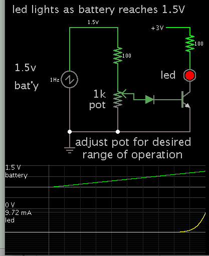
i am building an battery circuit and need an LED to turn on when the battery is at the correct voltage. I need help in choosing the right op-amp, configurate it as a comparator, and also than set up the reference voltage and the voltage in,and attaching it to the battery circuit.
 

Forget the LM386, it's an audio amplifier and won't work as a comparator. The LM741 needs a minimum of about 9V to work properly and has quite poor performance compared to dedicated and more modern comparators. What battery voltage are you monitoring? It may be easier to use another method to check the voltage. The problem with a comparator is it needs a voltage higher than the one you are monitoring to work so it's difficult to monitor it's own supply.

Brian.
 

i thought you could use any op-amp , and i have heard of people using an lm386 as an comparator? and also can't the ua741 be used as an audio amp as well?
 
Last edited:

Well, you might be able to use an LM386 with poor threshold detection and it you set it to high gain and you add a snubber at the output. It's intended to be used in low voltage gain circuits but provide high current output in a narrow bandwidth to drive a loudspeaker. For a comparator you really need high voltage gain and fast output switching.

In theory, you can use any op-amp but many have limited differential input voltage which means you can't use them as comparators unless you are working in a narrow voltage range and often they need high or split supply voltages. A purpose made comparator will have wide differential input range and the output will be a logic rather than analog signal. They are designed for different purposes but have a limited 'cross over' area where an op-amp might work as a comparator. It will never work the other way around, you can't use a comparator as an op-amp.

Brian.
 

Personally, I would consider to use an Arduino Nano (it cost $1.45 on some well known commercial sites).
If you look for "New Pro Mini atmega328 Board 5V 16M Arduino Compatible Nano NEW M43" you might find what you need.
 

i am improving an battery charger, have you ever heard of people charging alkaline battery, and the re-newit alkaline battery charger, or any of the standard alkline battery chargers? i need the voltage to be about 1.5 volts as the montoring voltage.
 

Actually you need to monitor the charge current to indicate the charge at the float voltage so that below this threshold, the charge is complete.
But you need a load to test the battery.
 

Hi,

There are opamps to be used as amplifiers.
And there are comparators to be used as comparators. They are specially made for it. Opamps are not made for it and may cause problems.

But back to your problem.
An arduino / Atmega128 has a built in comparator. So why use an external one?

But even better. They have built in ADC. No need to bother about adjusting trigger levels and hysteresis, you can all this do in software.

Klaus
 

We used to try to charge alkaline batteries about 40 years ago, it did not work. About 20 years ago rechargeable alkaline batteries were sold but they also did not work well.
Wikipedia says a partially discharged alkaline battery can be renewed (not re-charged) 10 times with less capacity each time but it might leak or explode while charging.
The expensive charger uses pulses, not DC so a comparator is probably not used.
 

yes i use pulsed charging , the main circuit is a 555 making the pulsed signal , i have actually used it to charge one 1.5 alkaline battery, it actually works , i just want a signal to turn off when its done charging or an LED when its at the right voltage, i know that alkaline battery charger uses a microcontroller and makes the pulses and monitors the voltages, i want to that without a microcontroller, i was thinking a comparator might work, but i didn't think about with the pulsed voltage it would work or not.
 
Last edited:

A good design can be made better with improved specs.
Recharging batteries whether they are technically primary or secondary can be modeled like charging a Capacitor with ESR and leakage R as a simple model. More complex ones have additional RC values,

Definition of the Charge OK and Battery Fail mode indicator are essential to all smart chargers.
This can be defined in many ways but the best would be a dynamic time dependent value rather than a static voltage. which can give erroneous results.

I would use the fact that batteries sharply change in equivalent capacitance ( kilofarads) and resistance (ESR & leakage).

Once you characterize the range of valid values for these and your detection method will be determined by these specifications.
e.g. pulse charge and voltage change above base voltage of the chemistry.. which is similar to the ESR of an LED above threshold voltage which is very predictable depending on the LED power value.

I could do this for you, but it would be better if you did this exercise to defining these Design Specs in order to improve the design results.

State : undercharged OK overcharged (fault)
Vmax
Vmin
Cmax
Cmin
ESRmax
ESRmin
 

on the above post i can get them values from a battery technical sheet? i was going to base the design off of this smart battery charger https://obrazki.elektroda.pl/2945700000_1450538576.gif which uses an window comparator , with op-amps as comparators or if i can't get this to work just make them out of transistors.


No you cannot get this experience from battery spec sheet but you can derive from new battery specs for mAh to to mWh to C and ESR from different C/10 c/20 load ratios for example.
It depends it you want a "Smart " charger or just a dumb charger.

If you have not understood my responses yet, let me say clearly that transistors will not give accurate detection alone, but that design uses a pot so you can calibrate a momentary precise level but that will drift with temperature from Shockley effect on Vbe.

So otherwise revise your requirements or your design so they meet or exceed requirements.
 

if i need a comparator would it just be better to use a chip just for use only as a comparator , instead of making comparators from transistors or even just op-amps?
 

An inexpensive LM393 dual comparator IC has two circuits, each with about 16 transistors and four diodes. An inexpensive LM339 has four of the same comparators. Since all the parts are on the same chip then they are all at the same temperature and the design allows the changes of the spec's of a part caused by temperature change to be cancelled by the change in the spec's of another part nearby on the same chip.
A comparator switches its output very quickly from almost 0V to as high as you want that is within its maximum voltage rating. But an opamp is slowed down to prevent it from oscillating when it has negative feedback and most have inputs and outputs that must be within certain voltage limits. Forget trying to design your own comparator made with transistors.
 

Simple battery monitor. LED lights as battery reaches 1.5V. The led needs a few volts supply. The diode in the bias wire causes more abrupt turn-on.


You don't need this if they found a way to make led's light at 1.5V. Such an led would be sufficient by itself.
 

can i use that above circuit in parrallel with the charging circuit , have the main pulsing circuit on the battery and than the led circuit on the battery, but because its also hooked up to the charging circuit, and the problem is the voltage would be more than 1.5 volts. So how could i integrate that LED circuit with my pulsating charging circuit, so when the led light turns on when the battery is at the right voltage?
 

Michael, can you clarify something please:

Are you trying to charge rechargeable batteries or 'renew' non-rechargeable ones?

There is some scope for putting power back in non-rechargeable (primary cell) batteries but the technology for monitoring the charge level is quite different. You have to aim for minimum ESR rather than maximum voltage and it requires a different approach to monitoring the battery state. A comparator alone isn't sufficient.

Brian.
 

renewing standard alkaline batteries, what circuitry do i all need , i know i need a pulsing voltage, and also maybe a comparator, is there anything else i would need to monitor the battery?
 

can i use that above circuit in parrallel with the charging circuit , have the main pulsing circuit on the battery and than the led circuit on the battery, but because its also hooked up to the charging circuit, and the problem is the voltage would be more than 1.5 volts. So how could i integrate that LED circuit with my pulsating charging circuit, so when the led light turns on when the battery is at the right voltage?

Your charger voltage will automatically drop to battery voltage which is too low. Therefore you need to draw from your main power source, and connect that where my schematic says 3V. My schematic only shows the concept of operation. I don't know the voltage of your power source. You need to ensure that volt levels are safe for components. For instance, adjust the value of the safety resistor so the led does not get overmuch current.
 

Status
Not open for further replies.

Part and Inventory Search

Welcome to EDABoard.com

Sponsor

Back
Top