Continue to Site

Welcome to EDAboard.com

Welcome to our site! EDAboard.com is an international Electronics Discussion Forum focused on EDA software, circuits, schematics, books, theory, papers, asic, pld, 8051, DSP, Network, RF, Analog Design, PCB, Service Manuals... and a whole lot more! To participate you need to register. Registration is free. Click here to register now.

DC motor noise removal

Status
Not open for further replies.

neazoi

Advanced Member level 6
Joined
Jan 5, 2008
Messages
4,123
Helped
13
Reputation
26
Reaction score
15
Trophy points
1,318
Location
Greece
Activity points
36,955
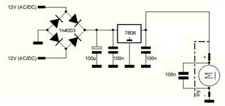
Hi I have this little circuit driving a small toy DC motor at a fixed 8v.
I want to minimize the RF noise coming out of the motor.
I have connected a 100nF across the motor contacts but it did not help much.
The noise radiates through the cables feeding the circuit with 12V (left of the bridge). It radiates all the way until the cables reach my lab PSU.
I was thinking of adding some kind of LC filter prior to the bridge circuit (I have many 10mH molded chokes that I can use for the purpose), but I am not sure if this will help.
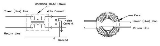
I do not want to use a common mode choke because these are too large for this project.
Any ideas?
 

Attachments

  • Capture.JPG
    Capture.JPG
    36.6 KB · Views: 123

Hi,

Can you post a photo of the capacitor attached to the motor?
Please try to add a second capacitor to the metal caee of the motor.

Klaus
 

... or better still, two capacitors, one from positive to the case and one from negative to the case. Ideally use ceramic types with very short wires.

Don't forget a common mode choke can be a simple as the motor wires passing through a ferrite bead.

Brian.
 

    neazoi

    Points: 2
    Helpful Answer Positive Rating
... or better still, two capacitors, one from positive to the case and one from negative to the case. Ideally use ceramic types with very short wires.

Don't forget a common mode choke can be a simple as the motor wires passing through a ferrite bead.

Brian.

So using a single ferrite bead and pass both motor leads inside it?
Should I ground the case?
How a second capacitor will prevent noise radiated from the wires?
Noise is mainly in the low shortwave range.
 
Last edited:

Suppressing radiated and conducted emissions is a healthy dose of trial an
error.

One thing I learned is not all manufacturers ceramic disks, for same C exhibit same
esr performance. So in our FCC work we made 50 ohm jigs and measured various
manufacturers. Quite a large variation we found. So start with datasheets then test.

Clues are lead wire diameter, span on disk electrode surface of attached wire....


Do you have to meet FCC part 15 ?


Regards, Dana.
No I don't have to meeτ the standard. This is just a hobbyist circuit. But because if might be placed in very close proximity to AM radios, I have to remove as much noise as I can.
As said, I detect noise at the wires going to the power supply connected to the circuit. This is noise that passes through the cables and radiated by them.
 

Think of the motor as being a signal source and the wires being the antenna. In most cases that means the source is in the center of a dipole, worst case being the wires head off in opposite directions but in most cases they will be close to each other so some cancellation will take place. The objective is to kill the signal before it gets out so the capacitors need to be as close as possible to the source. The motor's casing will be metal and the wires are unlikely to be internally connected to it as they normally go to the commutator brushes so keeping the case and both wires at the same signal potential will help to stop leakage. Yes, if possible ground the motor case and if possible pass both wires through a ferrite ring with the capacitors on the motor side of it. If you can get several turns around the ring, all the better.

Brian.
 

    neazoi

    Points: 2
    Helpful Answer Positive Rating
Think of the motor as being a signal source and the wires being the antenna. In most cases that means the source is in the center of a dipole, worst case being the wires head off in opposite directions but in most cases they will be close to each other so some cancellation will take place. The objective is to kill the signal before it gets out so the capacitors need to be as close as possible to the source. The motor's casing will be metal and the wires are unlikely to be internally connected to it as they normally go to the commutator brushes so keeping the case and both wires at the same signal potential will help to stop leakage. Yes, if possible ground the motor case and if possible pass both wires through a ferrite ring with the capacitors on the motor side of it. If you can get several turns around the ring, all the better.

Brian.
I added a small common mode choke to the DC cables that are powering the cirquit and the RF noise generated by the motor that was radiating from the DC cables were removed!!!

But I did not add any capacitors like shown in the schematic.
The schematic shows two capacitors connected to the common ground point but my circuit is powered by DC. How can I connect these capacitors in my circuit and what values (100nF?)
 

Attachments

  • common-mode-choke_schematics.jpg
    common-mode-choke_schematics.jpg
    16.6 KB · Views: 109

Hi,

we told you already. in several posts..
Please read the posts.

Klaus
 

Hi,

we told you already. in several posts..
Please read the posts.

Klaus
I am talking about a common mode choke used on DC. How are the capacitors of the common mode choke be connected, where their common point should be connected?
 

Hi,

as Brian told you:
You have to see the motor as the source of the noise.
Connect the two capacitors from metal motor case to the two wires. >This is the shortest way to short circuit the noise.

You are free to use capacitors else where ... with the effect of less suppression as the noise current will follow through the cables and use the cables to act as a noise transmitting antenna.

I just read through the thread. Our main recommandation was to use capacitors.. but you keep on coils.
The coils are not bad ... you can see the positive effect.
But the capacitors are better, because they short circuit the noise current while reducing the noise voltage.
So they reduce electrically (voltage) radiated noise and magnetically (current) radiated noise (because of short cable length).

Inductors make a high impedance path for the noise. This reduces noise current, but with increased impedance the noise voltage may increase. So basically they reduce magnetically radiated noise but they don´t reduce electrically radiated noise.

But as so often .. it depends on a lot of details .... like twisted cables, cable length... location of devices.. noise frequency range.....

Klaus
I have seen that of course but the capacitors alone were not effective. A near by AM radio received cables radiated noise. With the choke it did not. I just thought that I should i clude the caps near the choke but where to connect their common point?
 

but the capacitors alone were not effective
to find out why they was not that effective I asked for a photo.
Without the photo I have not enough information to improve the situation.

I could guess ... but I´m an electronics designer who does not want to guess. I want to understand, I want to know.
I´m not saying that this is the only best way. It´s just my way.

Klaus
 

Status
Not open for further replies.

Similar threads

Part and Inventory Search

Welcome to EDABoard.com

Sponsor

Back
Top