toyonline
Member level 2
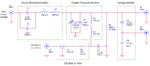
Hi, I am working on generating a high voltage RF signal floated on a small DC voltage. The basic network I used is attached. RF signal was generated by resonance LC tank, and DC was from a DC power supply to generate ~10V.
Since the RF I used is 5kVpp @ ~1MHz, to protect DC power supply, the DC was connected into the network through a filter.
The expected output (J2) was a RF floated on a DC voltage. But the problem is, the network seems sometimes alter my DC voltage measured. For example, after a period of use, when I turn off RF signal (switch off linear amp), measured output (purely DC) was 0.2V, and the orignial set one was 5V.
This phenomenon doesn't regularly appear. I cannot control, but it does arise somehow.
Does this suggest I should replace my caps like F1 or C7? any other suggestions?
Thx.
----Toyonline