AgnesAnna
Newbie level 6


Hi all,
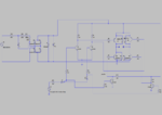
Here i have attached the controller circuit schematics(done in LTSpice) for single phase BLDC motor. The basic working is that based on the hall sensor signal, the current output of H bridge inverter should reverse. Across points A & B we'll be connecting the motor. Here the pulse signal represents the hall sensor output signal. The problem with this circuit is that when load (50 ohm) is connected across A & B, the required voltage and current signals are not getting. The voltage signal should be a square wave of 72 Vp-p (Vmax=36V) but what i am getting is a 4.8Vp-p square wave.Also, output of zener diode shold be 36V but 5V is the output with load.Without load its working fine. What could be the reason? Any suggestions to improve the circuit?
