Continue to Site

Welcome to EDAboard.com

Welcome to our site! EDAboard.com is an international Electronics Discussion Forum focused on EDA software, circuits, schematics, books, theory, papers, asic, pld, 8051, DSP, Network, RF, Analog Design, PCB, Service Manuals... and a whole lot more! To participate you need to register. Registration is free. Click here to register now.

Continuous time common mode feedback

Status
Not open for further replies.

Monady

Advanced Member level 4
Joined
Dec 1, 2008
Messages
109
Helped
12
Reputation
24
Reaction score
3
Trophy points
1,298
Activity points
2,151
Hi,

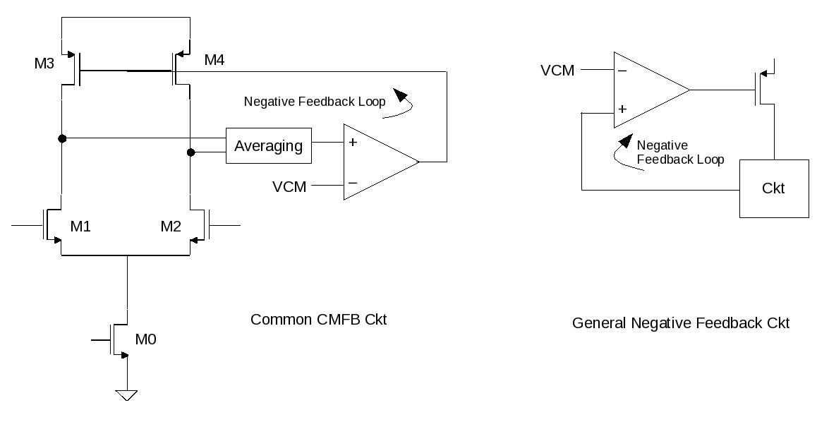
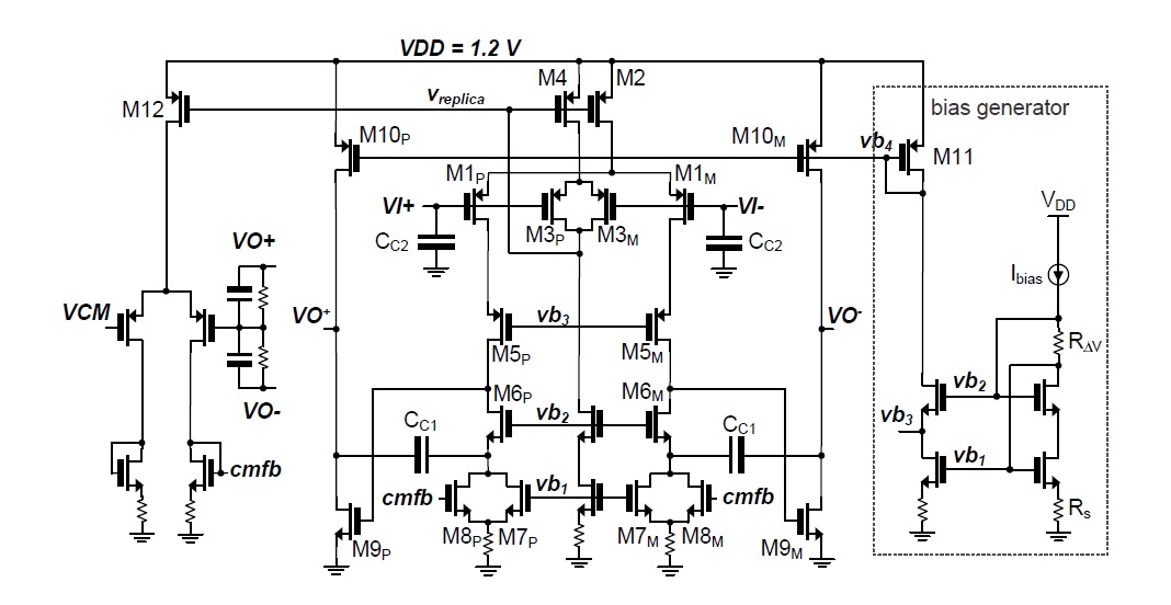
I'm going to design an opamp to be used in a continuous time system. I have seen several different structures for the CMFB part, including the one attached below. I want a CMFB which has a wide dynamic range, so I guess I need to use resistive averaging, but still I have a few questions:
What should frequency response of the CMFB circuit look like, I mean compared to the main opamp, should it have the same GBW, ...?
Besides, say in the case of the circuit shown below, for how much variation of the Vb1, CMFB should still be able to set the common mode of the output (VO+ and VO-) constant?
I have also seen some other structures that instead of using two diode-connected transistors in the CMFB, they used one single stage opamp (using just one diode connected), which one is more reliable?

Thanks!
 

Hi Monady,

What should frequency response of the CMFB circuit look like, I mean compared to the main opamp, should it have the same GBW, ...?

The frequency response of the CMFB ckt need not be same as that of the main ckt. You have to set a GBW depending upon how fast you want the CMFB loop to respond to any change in the output node. In general no specification is given for the CMFB network as it is not the main ckt. So as a designer we generally have to take a call depending upon our requirement. We also do a stability analysis of the CMFB loop (i.e. we do compensation there as well). Say if there is a change at the O/P, now if the CMFB loop is unstable then the O/P would never settle back to your desired value. Treat the CMFB loop as complete separate ckt.


Besides, say in the case of the circuit shown below, for how much variation of the Vb1, CMFB should still be able to set the common mode of the output (VO+ and VO-) constant?

Any change in Vb1 will have an opposite change in cmfb voltage. Say Vb1 increases the the current consumed by M7 would be more. Without CMFB the 1st stage o/p would fall and push M7 in linear. But with CMFB M8 will draw less current and keep the total current constant. Now how much change in V1 will make CMFB loop to respond is dependent on the off-set of the CMFB amplifier (the left side). How fast is determined by the GBW.

I have also seen some other structures that instead of using two diode-connected transistors in the CMFB, they used one single stage opamp (using just one diode connected), which one is more reliable?

I personally feel that having differential amplifier with diode connect load will reduce the gain in the CMFB loop. That means the O/P and VCM will have a static offset. Why not a normal single ended differential amplifier. Let me know your views.

Hope this will help ... :)
 
  • Like
Reactions: Monady

    Monady

    Points: 2
    Helpful Answer Positive Rating
Thanks for your comments, they were really helpful. But a few questions:

We also do a stability analysis of the CMFB loop (i.e. we do compensation there as well). Say if there is a change at the O/P, now if the CMFB loop is unstable then the O/P would never settle back to your desired value. Treat the CMFB loop as complete separate ckt.

I didn't get it, for a CMFB like this how you can compensate it? There is also one issue with a CMFB I designed, one is similar to the one in the pic I posted before, that CMFB and the whole opamp work when I put them in a bigger circuit, but problem is when I change the Vb1 by 50 mV from the nominal value, the common mode voltage of the output would be off by like 70mV, which is not tolerable in my application. No matter how I play with the sizing of the transistors in the CMFB circuit, it won't help solving the problem.

The other CMFB I used is a single ended differential amplifier. This one can tolerate variation of the Vb1 by like 200mV and still common mode of the output is the desired one (by testing the opamp by itself). But when I put the opamp in a bigger system I see that output of the opamp has ringing. Which shows that problem is due to the CMFB circuit.

The thing is when I test the opapm by itself I use ac analysis and the CMFB part has no negative effect on the frequency response, and also by applying a small signal input I see that circuit works properly.

The other thing is, to design this CMFB I size the M12 half the M2, and the one connected to CMFB equal to the M8p. So the CMFB would work based on the current mirroring, I wonder if it's the right way or not. I couldn't find a design procedure for the CMFB part for a circuit like this please let me know if you're aware of any paper or something.
Thanks


About stabilizing the CMFB please have a look at the pis attached. I think stability analysis should be done in any negative feedback loop. Please let me know your views.
You need to treat the CMFB as the ckt under test and rest as a load to it. Identify a high impedance node (the i/p node of the CMFB amplifier) to break the loop and check the the open loop gain and PM of the CMFB loop. May be the ringing will reduce if stabilized (It would be better if the system level diagram is given)

and for you circuit do you need M7?? I feel that M8 should be sufficient. Again as you have mentioned that the circuit is fine stand alone the ckt should work fine in the system ( if you have applied similar load and input during stand alone simulation)

The sizing of M12 and the one connected to cmfb should be fine from current distribution point of view. I will try to search any paper for the same and let you know.
 
  • Like
Reactions: Monady

    Monady

    Points: 2
    Helpful Answer Positive Rating
Status
Not open for further replies.

Similar threads

Part and Inventory Search

Welcome to EDABoard.com

Sponsor

Back
Top