Continue to Site

Welcome to EDAboard.com

Welcome to our site! EDAboard.com is an international Electronics Discussion Forum focused on EDA software, circuits, schematics, books, theory, papers, asic, pld, 8051, DSP, Network, RF, Analog Design, PCB, Service Manuals... and a whole lot more! To participate you need to register. Registration is free. Click here to register now.

Collins 51S-1 fix

Status
Not open for further replies.

neazoi

Advanced Member level 6
Joined
Jan 5, 2008
Messages
4,123
Helped
13
Reputation
26
Reaction score
15
Trophy points
1,318
Location
Greece
Activity points
36,955
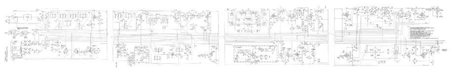
I have a Collins 51S-1 receiver here for fixing and it does a weird thing.
At random intervals the frequency is hopping back and forth a few 100s of Hz and more rarely a few KHz.

I suspected some problem with the voltage so I I checked:

The output signal of V15 [150v fed to it] (VFO-LC) and it hops when the receiver reception hop occurs.
The output signal of v3 [150v fed to it] (17.5MHz-XTAL) and it stays stable when the receiver reception hop occurs.
The output signal of v2 [150v fed to it] (HV XTAL osc) and it stays stable when the receiver reception hop occurs.
The output signal of V15 [150v fed to it] (BFO-XTAL) and it stays stable when the receiver reception hop occurs.

They are all connected to the 150v +B.
Notice that all the crystal oscillators stay stable but the main VFO hops.
This is expected because the crystal oscillators frequency does not vary much with minor variations of the +B. However the VFO frequency does.

Now, I connected the +B to the scope and waited for the next frequency hop to occur. When it did, the +B voltage changed by 2 to 2.5v. Bingo!
The bias reads -39v from the -37v nominal, so this is ok.
But, the 150v +B actually measures 171v whereas the 140v +B measures 160v.

I replaced the main reservoir capacitor (c182) just after the +B diodes, with three news ones, but again the problem was there. So I know that this capacitor does not cause the problem.

What else can I check?
There are some other electrolytics that look a bit popped out (in their rubber terminal) but they are not in places that should affect +b
 

Attachments

  • 51s-1_sch.png
    51s-1_sch.png
    1.4 MB · Views: 159

Have you looked for a connection between the problem and the signal going through the unit?

In other words, could the problem be triggered by:
* volume of incoming signal
* amount of modulation
* multipath
* transients
* stereo content
* hunting between mono vs stereo
etc?
 

Stereo !? Collins 51s is a CW/SSB/AM receiver..

https://collinsradio.org/archives/manuals/Collins51S-Receiver.pdf

I would check the VFO's DC stabilizer Zener diode CR502 and also the series diode CR501...
The radio has a jack to bypass the VFO signal and drive it's third mixer with an external VFO. I did exactly that in a new test, driving it with a DDS VFO. The reception now was super stable and no weird frequency "hops" occurred.

In fact, because of the tiny leakage from the bypass jack, I could hear the DDS beating with the internal crystal calibrator of the radio and also the VFO at the background, beating at a slightly different tone. The VFO beating was adjustable by turning the VFO tuning knob but the DDS one was only adjustable by tuning the external DDS. So I knew which signal is which. And of course the internal VFO beating was hopping around whereas the DDS was not.

So I have verified it is a problem caused by the VFO of the radio. This means that either there is a problem with +B (150V), or there is a problem with the VFO circuit.

I have also replaced the tube in the VFO. The previous owner had put an 6AU6 tube there instead of the original 7543 (they are pretty much interchangable according to this https://www.radiomuseum.org/tubes/tube_7543.html), and I replaced it with a brand new 6AU6WB, just to make sure it is not because of the tube.

Since the hopping frequency behaviour happens even when the radio is not shaken but paced put, I think it is not a cold joint inside but an electronic issue. They really wound around terminals the cables and component leads in these sets, so I do not think it is a cold joint.
If there is a problem with the VFO circuit, the only components I can think of myself, like you told me, is these two series zeners.

I cannot find any datasheet for them, do you know what are their values?

Can it be that because the +b is measured at 170v instead of the nominal 150V, that the zeners are pushed hard and heated to the point that they behave abnormally?

Before I open the extremely hard to remove VFO, I am thinking of building an external 150v PSU for it, and test it with it's own PSU, just to make sure it is not a PSU problem in the radio, and to verify it's behaviour on the nominal 150v.

What do you think of the above?
 

I don't know either what is the regulated voltage of the 1N409 Zener diode. The newer 1N4099 have voltages between 1.8V and 100V.

In the datasheet of the 7543 tube is mentioned that the screen voltage (Grid 2) should be between 100V and 150V.

Using a digital voltmeter check the DC voltage across those diodes, and see if the voltage is stable.
Using an external +150V supply for B+ is a good idea..
 

    neazoi

    Points: 2
    Helpful Answer Positive Rating
I don't know either what is the regulated voltage of the 1N409 Zener diode. The newer 1N4099 have voltages between 1.8V and 100V.

Using a digital voltmeter check the DC voltage across those diodes, and see if the voltage is stable.
All the references I find show this 1N409 as 1N4099.
That means a 6.8v zener. The 1n4131 is a 75 volt zener. I do not know why they have placed two of these in series.

BUT, I know (and please correct me if I am wrong) that if the voltage across a zener is lower than it's rated voltage, the zener will not conduct.

Given these points, I lowered the voltage to the VFO by increasing R62 from 1k to 56k. This brought the 169v feeding the VFO down to 65v.
Since one of the two series zeners are rated to 75v, with 65v (actually lower than that cause there is an additional 33k R503 inside the VFO) the series zeners will not conduct anymore and regulation will be ceased.

Am I thinking right on the above?

The VFO still operates and with rough tests I did not find any decrease in receiver sensitivity. VFO linearity (dial linearity) has not changed. Most importantly, I cannot detect any frequency jumping anymore.

I will do more extensive tests on these to be sure. I will also see the differences in the mixer products and the levels of them just to be sure. But removing and dissasembling the VFO in this radio needs ruining it (cut lots of cables) and dissassemble the mechanical gears, it is just so difficult. Not only that, but since we cannot find the actual voltage value of the 1N409, it would be impossible to replace that part.

So with this easy fix I did, I would like your opinion about my thinking on switching-off the zeners that way and disabling them effectively from the circuit.
 

Attachments

  • 1N4131.pdf
    112 KB · Views: 112

To be honest, I'm not sure why the screen grid is stabilized but not the anode supply, stabilizing both would seem the best solution. I'm guessing the intention is to keep the voltage at about 20V below the anode so if the supply is 150V and lets say the VFO draws 5mA, the anode would be at about 150 - (.005 * 1470) = 142V so the combined Zeners would be about 112V. That would make the 1N409 voltage 122 - 75 = 56V.

They certainly should be conducting or they wouldn't be fitted.

I have never come across faulty diodes that jump between two voltage before, my guess is the different tube and possibly excess supply voltage is causing some modal jump in the oscillator, possibly instability at a completely different frequency that changes the bias conditions but doesn't pass through the output filter.

Brian.
 

    neazoi

    Points: 2
    Helpful Answer Positive Rating
To be honest, I'm not sure why the screen grid is stabilized but not the anode supply, stabilizing both would seem the best solution. I'm guessing the intention is to keep the voltage at about 20V below the anode so if the supply is 150V and lets say the VFO draws 5mA, the anode would be at about 150 - (.005 * 1470) = 142V so the combined Zeners would be about 112V. That would make the 1N409 voltage 122 - 75 = 56V.

They certainly should be conducting or they wouldn't be fitted.

I have never come across faulty diodes that jump between two voltage before, my guess is the different tube and possibly excess supply voltage is causing some modal jump in the oscillator, possibly instability at a completely different frequency that changes the bias conditions but doesn't pass through the output filter.

Brian.
When you say that they certainly should be conducting or they wouldnt be fitted, you mean that the way I disabled them (did I?) by lowering the voltage below their threshold would cause problems leaving them there without conducting?

The way I think of it, with this mod, are two series zeners non conducting, hence they have no effect in the circuit. Am I right?

Set aside the different oscillator level and linearity, I focus just in the regulation to cope with the frequency problem. Btw, the osc was jumping even at the proper 150v.
 

What I meant was Collins fitted them to stabilize the screen grid voltage, not to protect against any over-voltage condition so in normal operation they should be passing a few mA. If you have lowered the supply below their Zener voltage they would serve no purpose so I guess the supply should be higher. What voltage do you measure across each diode?

Brian.
 

    neazoi

    Points: 2
    Helpful Answer Positive Rating
What I meant was Collins fitted them to stabilize the screen grid voltage, not to protect against any over-voltage condition so in normal operation they should be passing a few mA. If you have lowered the supply below their Zener voltage they would serve no purpose so I guess the supply should be higher. What voltage do you measure across each diode?

Brian.
I can't measure anything, this is the point. These are inside the VFO screened enclosure. To open the enclosure requires disassembling nearly half of the receiver, including the mechanical gears and cutting off quite a few cables. This is just too difficult. Not only that, but since we do not know the exact voltage of one of the zeners, replacing them with a proper type is not easy. I think two are inside there in series for some kind of temperature compensation.

So I am trying to "fool" the VFO and disabling these zeners by feeding lower VFO voltage externally, which of course feeds lower plate voltage as well and thus lowers the VFO output.

At 65v on the vfo (by increasing R62 to 57K) I measure about 1.26vpp of VFO output.
Before this modification, I measured 4.5vpp of VFO output.

The waveform distortion is visually the same on both signals.
I would expect a level of receiver sensitivity, because of the lower VFO output, and there is some, but it is not big at all and the receiver has a lot of gain headroom.
The dial linearity is still excellent.

I know it is not the proper way of fixing things, but these points above show me that with a tiny gain loss the vfo can operate at less than half the voltage. Maybe I am missing something and you may have some comments on this.


Aside from the above, I see a weird thing.
I have installed a switch to instantly compare between 1K and 57K for the R62.
When I first switch on the radio and get it heated, the frequency is at a point. Then I instantly change from 57k to 1k (to bring the vfo voltage up again) and then instantly change again to 57k. After this, the vfo changes frequency by some KHz and stays there.
It is like, once it is fed with high voltage, then it locks there no matter if the voltage goes down again.
Weird isn't it?
Even more weidness, when I momentary press this switch and leave it again open, the frequency in the open position (low voltage) changes a bit. When I do the procedure again, the frequency changes more, then more and more up to a point. This raises my speculations for faulty zeners...

Oh and I would love if you could suggest me a 65v regulator, to feed the VFO, it would solve also the VFO's tendency to deviate when the mains voltage fluctuates (yes it does when I switch on high loads at home).
Maybe 2 or three LM317 in series? Or external zeners?
 
Last edited:

I wouldn't use big regulators when the current is so small. Just use a Zener diode (62V, 68V and 75V are all commonly available). Measure how much current the VFO draws from your external supply, add say 2mA for the Zener to pass and use (R=Vdrop/I) to work out the optimal series resistor needed.

Brian.
 

    neazoi

    Points: 2
    Helpful Answer Positive Rating
I wouldn't use big regulators when the current is so small. Just use a Zener diode (62V, 68V and 75V are all commonly available). Measure how much current the VFO draws from your external supply, add say 2mA for the Zener to pass and use (R=Vdrop/I) to work out the optimal series resistor needed.

Brian.
This is a drop from 170v down to 65v on the current the 6au6 draws at that voltage. Do you think a zener can handle that much large voltage drop?
 

This is a drop from 170v down to 65v on the current the 6au6 draws at that voltage. Do you think a zener can handle that much large voltage drop?


It depends on the Watt rating. If it gets too hot, install a transistor arranged to act as a shunt regulator. Build a bias network incorporating the zener. The transistor must be rated for sufficient Watts, perhaps with heat sinking added.

Or, string together several zeners to share heat dissipation while attaining a desired zener voltage.

Prolonged high temperature can alter a zener diode's operating characteristics permanently. I read about an oscillator project which used a 'cooked' zener. You were supposed to take a good zener and heat it deliberately so that its knee (turn-on voltage) was not so sharp. This created a range for adjustment where oscillations could occur, although it became useless for regulation.
 

    neazoi

    Points: 2
    Helpful Answer Positive Rating
Stabilizing the screen (Grid 2) of a tube is a very old approach, used before semiconductors and Zener diodes. Initially were used stabilizer tubes as OB2, OA2, OB3, etc.


Stabilizing the screen of the tube is very important if the tube is used as an oscillator.
You can do an experiment, if you have this kind of circuit. Vary both voltages, plate (anode) and screen (grid 2), and you will see that the frequency of the oscillator is changing much more when vary the screen voltage. This need to be stabilized.

On the Collins schematic, the sign L near the Zener diode was used before the Zener simbol used today. So, the diodes are shown in the right place.
More Zener diodes are placed in series to increase the stabilized voltage accross them.

You have to replace them with newer diodes, and the circuit will work as before.
I am glad that my solution works..
 

This is a drop from 170v down to 65v on the current the 6au6 draws at that voltage. Do you think a zener can handle that much large voltage drop?
It doesn't have to. The series resistor does the dropping. If you use a 68V Zener and say 2mA current, it only dissipates (68 * 0.002) = 0.136W

I agree with Vfone about adding diodes in series but it's worth remembering that the receiver is at least 40 years old and maybe as many as 50. In those days, Zener diode technology wasn't as advanced as today and what was available to use was limited, especially at higher voltages.

Brian.
When it comes to calculations I am really behind... So I would greatly like your help on this to find the practical values to try.
Basically anything from 41v to 70v will work.
So we have to drop 170v down to 65v, or near.
Now I am using a 56K resistor to drop to 65v.
So I guess I have to use a little smaller resistor and then a 68v zener and that's it?
Maybe opt for a few volts more than the voltage of the zener, say 75v or so, so that the zenner does not get heated.
Will such an approach work? Any circuit values would be helpful
Currently
 

As I mentioned in #5 have to use a Zener closer to 100V, because that is the minimum grid 2 voltage range, according to the datasheet (100V to 150V).
Before Zener diodes, other old VFO schematics use OB2 voltage regulator tube which has about 108V.
 

As I mentioned in #5 have to use a Zener closer to 100V, because that is the minimum grid 2 voltage range, according to the datasheet (100V to 150V).
Before Zener diodes, other old VFO schematics use OB2 voltage regulator tube which has about 108V.
You can't do that. If you feed 100V to the VFO, you will re-introduce the frequency hopping problem, because the faulty internal zeners will start to conduct again.
I now drive the +B with 65v in the anode and in the grid it is less because there is an internal 33k in series with the grid internally. The 75v zener sould not conduct, so no matter what the other zener value is, it should not conduct neither. That way I disable the internal zeners.

Neither the linearity, nor the distortion of the VFO is affected by driving it in that low voltage. Only output level and frequency is affected which has a slight decrease in receiver gain, very slight. I compensated the level by increasing the receiver gain set potentiometer. AGC does not seem to be affected. I re-calibrated the receiver for zero beat, to re-ser the frequency again.

What I am trying to do now, is to further stabilize this 65v that feeds the VFO with an external zener. This should provide both grid and anode voltage stabilization. So in fact this sould be better than the original.
 

Indeed an OA2 or OB2 would be more historically correct for that receiver but a Zener will work just as well in a much smaller space.

The calculation is quite simple once you realize what the Zener actually has to do. Consider that there are two variables to be aware of, one is fluctuations in the supply voltage and the other is the natural variation in current drawn by the VFO as it tunes across its frequency span. If both of those were constant, you could simply use a resistor with no Zener at all because the voltage dropped would always be the same. So what the Zener has to do is compensate for the variations. In theory, the Zener only has to pass the difference in current between maximum supply/minimum current (most voltage at the VFO) and minimum supply/maximum current (least voltage at the VFO) but in practice adding a mA or so should be added to provide a safety margin.

So what you need to do is hook up a stable supply, I'm going to suggest 100V as per vfone's post #5 and #17 then measure the max and min current drawn by the VFO as it tunes across its range. Then take your max and min supply voltage, based on anticipated mains variations.

The optimal resistor value is then the maximum supply voltage - 100
divided by the maximum VFO current + 1mA (the 1mA is the safety margin)

The calculation should give the resistor value that makes the Zener pass 1mA when the supply is lowest and the VFO draws most current. If the voltage rises or if the VFO draws less current, the Zener will conduct more to keep the voltage stable.

Brian.
--- Updated ---

We cross posted - you can use a lower Zener voltage than 100V with the same calculation but my guess is the existing Zener diodes are not to blame but using the wrong tube is causing some unwanted spurious oscillation at a frequency out of filter range. The change in current as it bursts into oscillation will change the apparent voltage feeding the VFO.

Brian.
 

It would be a nice test to find the original 7543 tube and hook it up. That would be a more proper solution. I am going to do that, no matter if enjoyed the current fix.
 

Status
Not open for further replies.

Part and Inventory Search

Welcome to EDABoard.com

Sponsor

Back
Top