Continue to Site

Welcome to EDAboard.com

Welcome to our site! EDAboard.com is an international Electronics Discussion Forum focused on EDA software, circuits, schematics, books, theory, papers, asic, pld, 8051, DSP, Network, RF, Analog Design, PCB, Service Manuals... and a whole lot more! To participate you need to register. Registration is free. Click here to register now.

Circuit for the Protection of CAN bus from high voltage 70V

newbie_hs

Full Member level 1
Joined
Mar 4, 2023
Messages
96
Helped
1
Reputation
2
Reaction score
1
Trophy points
8
Activity points
770
I am using ISO1042 in my design. My can bus voltage can go up to 70V.

I checked the reference design provided by TI .The ESD diode(CDSOT23-SM712) specified by TI can stand a reverse voltage of 12V (Max).

I checked for other ESD diodes which can with stand a reverse voltage more than 70V.I am not able to see an ESD diode with standoff of 70V.

The maximum clamping voltage allowed is 70V


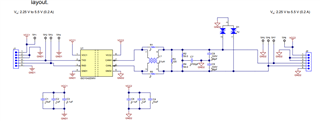
May I know is there any other method to protect the CAN bus from high voltage.
 
Whatever clamping method you use, the "standoff" voltage must be lower than the transceiver "absolute maximum voltage", so something is wrong with your requirements.
For TVS diodes and varistors, the maximum clamping voltage depends on the current, and can be much higher than the standoff voltage. If the bus margin allows for series resistors, they can be used to reduce the maximum current, which also reduces the clamping voltage.

It is also possible to have a "series" protection.
I have used two N-channel MOSFETs between bus and transceiver, with a gate voltage set so the MOSFET is normally fully on, but switch off when the drain (= CAN bus) voltage goes over a certain value. The sources are connected to the CAN transceiver. You still need some TVS diodes or similar to clamp the MOSFET Vgs and Vds voltages, but the maximum bus voltage can be higher than the maximum transceiver voltage.
 
What's your battery, 24V or 60V? As already explained by std_match, you can't have full IC protection and up to 70 V bus voltage with a simple circuit.
 
Thank you.
Battery is 70V.I am looking for a protection circuit.I did not completely understand the circuit by explained by std_match. If I am getting a circuit diagram it will be very helpful.
 
Thank you.
Battery is 70V.I am looking for a protection circuit.I did not completely understand the circuit by explained by std_match. If I am getting a circuit diagram it will be very helpful.
Perhap you mean an isolation barrier of 70V?
 
Isolation barrier is kV rated. Automotive CAN has to deal with high differential bus voltage under fault conditions, but you need an exact specification to design appropriate protection.
 
Checked with BMS team maximum battery voltage is 120V.
May I know adding series resistors will work or not as shown below.
1694499469925.png


May I know your thought's.
Can I add some 1K,
Will it cause any termination issues
 
Hi,

the SN65HVD231 datasheet specifies max 16V at the CAN bus line.

Some times can lines may get sorted to battery.That is 70V
This is what you need to avoid in first place.

If you short 70/120V to the CAN bus, then I guess it´s hard (maybe impossible) to handle this.
* If you don´t use series resistors then the current will become high enough to maybe destroy the protection circuit (high energy) maybe destroys the wires, maybe destroys other electronic parts, will generate a lot of heat / fire.
* if you use series resistors then the data integrity will suffer. The CAN bus simply is not made for this.

High voltage combined with low resistance will cause high power dissipation.There is no way around.

If you can´t avoid the connection between battery and CAN bus, then maybe the only solution is to galvanically isolate the CAN bus system from the battery system.

Klaus
 
The MOSFET solution I mentioned was for a similar application, so it may be useful here. I will make a simple drawing and post here. Be aware that the protection have some capacitive loading on the bus, so it can affect the maximum bus speed.
Which transceiver is used? They are different in posts #1 and #10.
Is it enough to protect for 120V of only one polarity? Positive only?
 
Remove the "optional" remark on the 33V TVS. It is needed together with the 10V Zener to clamp the MOSFET gate voltage relative to ground. A 36V Zener or TVS between the gate and ground is also possible,
Without gate clamping relative to ground, positive edges of transients on the CAN bus can pass through the MOSFET. It is better to prevent them than to only rely on the 33V TVS.
--- Updated ---

I recommend using both the 33V TVS and a separate clamping 36V TVS or Zener between the gate and ground. It is the gate-source capacitance that otherwise can keep the MOSFET on for a while when there is a positive transient on the CAN bus.
 
Last edited:

LaTeX Commands Quick-Menu:

Part and Inventory Search

Welcome to EDABoard.com

Sponsor

Back
Top