Continue to Site

Welcome to EDAboard.com

Welcome to our site! EDAboard.com is an international Electronics Discussion Forum focused on EDA software, circuits, schematics, books, theory, papers, asic, pld, 8051, DSP, Network, RF, Analog Design, PCB, Service Manuals... and a whole lot more! To participate you need to register. Registration is free. Click here to register now.

Cascading DS1669 to achieve more steps?

Status
Not open for further replies.

neazoi

Advanced Member level 6
Joined
Jan 5, 2008
Messages
4,123
Helped
13
Reputation
26
Reaction score
15
Trophy points
1,318
Location
Greece
Activity points
36,955
Hi I would like to cascade four DS1669 digital potentiometers to achieve a 256 step one. Is that possible and how?

I do not mind the final value of the composite potentiometer as this will be used as a potential divider to drive a varicap. What I do care is to increase the number of steps so as to increase the "resolution".

Maybe another chip can do it but it has to have the up/down buttons not I2C or other digital control and be easily solderable (not QFN)
 

I wouldn't say it's impossible but it would certainly be difficult. I don't think it feasible to increase the resolution directly but you could (accepting the limitations of the device) connect the output of one to the input of another. You would need three DS1669, one to set the upper voltage and one to set the lower voltage for a middle device, taking the output from the wiper of the middle one. Driving the up/down controls would require additional counters and logic though and be quite complicated.
A small micro and DAC is a better solution, more versatile, far less complicated and certainly much cheaper.

Brian.
 

    neazoi

    Points: 2
    Helpful Answer Positive Rating
Maybe another chip can do it
I guess so. Did you do an internet search?

If you show a schematic with your idea, maybe we can find ways to improve it.

Klaus
 

    neazoi

    Points: 2
    Helpful Answer Positive Rating
I do not have a circuit in mind, but thank you all.

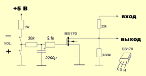
However I had also found another way to create an "electronic potentiometer". See the attached image.
The only thing that worries me is how fast the capacitor charge will be drawn and hence detune the varicap to be driven with this potentiometer.
 

Attachments

  • 79493908.gif.11ac653930c36b44e66aea4b3489c8b9.gif
    79493908.gif.11ac653930c36b44e66aea4b3489c8b9.gif
    8.8 KB · Views: 122

Hi,

I recommend to read the datasheet and/or other material provided by the capacitor manufacturer regarding "self discharge" or "leakage current".
Then consider all additional leakage currents: PCB leakage currents (flux residuals...), wiring, switches, humidity and temperature effects...

I can´t say whether your approach is good or not...
It´s not that easy to get a really stable voltage over time.

Klaus
 

    neazoi

    Points: 2
    Helpful Answer Positive Rating
Adding to Klaus's comment - don't forget the FET isn't a perfect voltage to resistance device and it also has a gate threshold voltage before the resistance between drain and source starts to drop.

My guess - and that is all it is - would be that you would notice a considerable drift in tuning almost immediately. Assuming whatever drives the voltage across the capacitor doesn't leak charge away itself, and the FET doesn't draw any drain current, experiment by charging a 2200uF capacitor then every few minutes measure the voltage with a DVM to see how long it maintains the voltage. The DVM itself if only connected a few seconds will have negligible effect on the discharge.

Brian.
 

Short answer is yes but it may not be monotonic. Do the error analysis,
and draw out the step uncertainty due to errors coming out of the pots.

You can get 16 bit resolution easily out of most onchip PWM's, and with proper
filtering eliminate the clock noise. In modern amateur radios there are PWM circuits,
even though they have high sensitivity RF circuits.


Regards, Dana.
 

I think all thats needed is a simple MCU and SPI DAC. That way there is no signal on the SPI bus except when changing the voltage. I'm picturing a simple PIC, maybe an 8-pin one, two switch inputs for up and down, three pins for SPI and using internal EEPROM to store the setting when the power is off. Even 10-bit PWM, which most MCUs can manage might be too coarse for tuning, they would give 1024 tuning steps but the beauty of serial DACs is you can get as many bits as the IC can manage with no additional wiring. The cheap MAX5316 comes to mind, it has 16-bit resolution so there would be 65536 voltage steps of 76uV from a 5V supply.

Brian.
 

Status
Not open for further replies.

Part and Inventory Search

Welcome to EDABoard.com

Sponsor

Back
Top