Continue to Site

Welcome to EDAboard.com

Welcome to our site! EDAboard.com is an international Electronics Discussion Forum focused on EDA software, circuits, schematics, books, theory, papers, asic, pld, 8051, DSP, Network, RF, Analog Design, PCB, Service Manuals... and a whole lot more! To participate you need to register. Registration is free. Click here to register now.

[SOLVED] Can this this high frequency inverter have modified design

Status
Not open for further replies.

treemon

Member level 3
Joined
Nov 2, 2022
Messages
60
Helped
0
Reputation
0
Reaction score
4
Trophy points
8
Activity points
402
IMG_20221102_091928_828.jpg

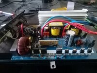
I have this chinese 48v to 220 VAC/50Hz pure sine wave (by cnswi power) inverter, this inverter recently stopped working after its mosfet and igbt were burnt, now I am trying to repair.

Design of this inverter is typical type, on low side 2 series transformer driven by 8 mosfet at 31khz, their output is then rectified and I get aboud 350 VDC.

This high VDC is then inverted using a H-bridge (4 igbt) and subsequently fed to a LC filter to remove high frequency carrier waves, and I get 50hz pure wave. H-bridge is driven using a custom made riser board (visible on image, its not EGS002).

High side IGBT are heating up (H-bridge), so my question is, instead of rectifying and later using h-bridge topology, can I directly generate pure sive wave on low side itself (2 transformer), as these tranformers are high frequency capable and should be able to handle carrier frequency by an EGS002 driver board.

H-bridge are risky thing I feel and can get shorted easily, that is why I wanted to eliminate them. Is there potential drawback of this modification?

Thanks in advance
 
Last edited by a moderator:

haha - can you modulate the HF transformers to get 50Hz out ? - short answer = no

an H bridge or unfolding ckt is always needed - unless you revert to a 50Hz transformer ....
 

haha - can you modulate the HF transformers to get 50Hz out ? - short answer = no

an H bridge or unfolding ckt is always needed - unless you revert to a 50Hz transformer ....


HF transformer will be operating at the base frequency of 23 khz (of EGS002), this is a SPWM, so it periodically (at 50hz) varies duty cycle, to make a sine wave.
 

You forget that a high frequency transformer can't transfer pwm voltage with asymmetrical duty cycle. Positive and negative voltage*time area must be balanced for every cycle, otherwise it saturates. To transfer 50 Hz spwm voltage, the transformer must be designed for 50 Hz flux.
 
You forget that a high frequency transformer can't transfer pwm voltage with asymmetrical duty cycle. Positive and negative voltage*time area must be balanced for every cycle, otherwise it saturates. To transfer 50 Hz spwm voltage, the transformer must be designed for 50 Hz flux.

Thank you, this was the exact the validation I was looking for
 

Status
Not open for further replies.

Similar threads

Part and Inventory Search

Welcome to EDABoard.com

Sponsor

Back
Top