Continue to Site

Welcome to EDAboard.com

Welcome to our site! EDAboard.com is an international Electronics Discussion Forum focused on EDA software, circuits, schematics, books, theory, papers, asic, pld, 8051, DSP, Network, RF, Analog Design, PCB, Service Manuals... and a whole lot more! To participate you need to register. Registration is free. Click here to register now.

Can I use only lower side of ir2110?

Status
Not open for further replies.
Connect pin 3 VCC of the IR2110 to +12V or +15V. Also, connect a 1k resistor between the gate and source of the MOSFET.

Also, I noticed you used a 400V 1000u capacitor for filtering. You should have an inrush limiter of some sort at the input. Also, connect the negative of the bridge rectifier to the IR2110 ground.

You also need to connect a freewheel diode across the motor.

Hope this helps.
Tahmid.
 
  • Like
Reactions: ta2mix

    ta2mix

    Points: 2
    Helpful Answer Positive Rating
    V

    Points: 2
    Helpful Answer Positive Rating
alot of people write for about bootstrap calculation but and I think alot of people couldnt understand it. can you calculation a real example and figures for all forum members.. because some members do not know to read datasheet or forum link

yes my capacitor very big but When the electricity goes off.. treadmill should not stop suddenly .to be larger than the capacitor problem?

also How do I calculate the value of gate resistance

I used between the gate source resistance 10k

six ir2110 and 4 ir2117 burned then my motor worked with ir2110 lov side

Thank you undivided attention
 
Last edited:

Bootstrap capacitor is required for high side driving. You mentioned in the last post that you're using only low side. So, here you don't need the bootstrap circuitry. As far as calculations are concerned, they are provided in the IR application notes, but they seemed too complicated due to a number of parameters involved such as the capacitor leakage which may be too difficult to find out especially if it's not branded and doesn't have a datasheet. You can also use rough values from around 1uF to 100uF depending on the frequency and duty cycle - the time for which the high side MOSFET must be kept on.

Might be that the capacitor can not supply enough current for long enough. Motors draw a lot of current, especially DC motors.

The gate resistance may be selected roughly through an idea of the frequency used and the required turn on/off time(s). What frequency are you using? For upto maybe 100kHz or thereabouts, you can use a 10 ohm resistor.

10k is a little too large for gate source resistance. Decrease it to about 1k-4.7k.

Hope this helps.
Tahmid.
 
  • Like
Reactions: ta2mix

    ta2mix

    Points: 2
    Helpful Answer Positive Rating
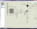
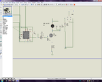
and sometimes corrupted the mosfet, ir2110 garbled. Adsız.png

then I changed circuit connect the D6 and R21 Adsız.png

How about this making protection?
 

That is not very good. If you connect D6, the MOSFET gate capacitance will no longer be discharged by the driver in the IR2110 but through the 1k resistor from gate to source. This is going to be slow and in a high frequency circuit, you don't want that.

However, at a lower frequency, it won't be too problematic. What frequency are you using?

One thing I've noticed in the diagrams is that the IR2110 ground and the MOSFET ground are not connected together - the IR2110 and the MOSFET have different grounds. They should be having the same ground connection.

Hope this helps.
Tahmid.
 
  • Like
Reactions: ta2mix

    ta2mix

    Points: 2
    Helpful Answer Positive Rating
yes you tru but hove can I protect ir2110?

and r17 0.05R resistor for current monitor circuit.
 

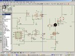
yes I change com pin2 to mosfet source pin connect and I new desing for protect ir2110
ir2110 protect.JPG

if the MOSFET fails d7 zener and fuse2 work or if the ir2110 fail D8 AND FUSE1 WORK
is it true?
how can I colculate fuse?
I think when the ir2110 out PWM signal is broken, mosfet broken to. I used Vdd= 5V Vcc=15v 20khz
 
Last edited:

Low side is where load is taken from drain and source is connected to ground. Here, VGS is always eg 10v as source is connected directly to ground.


Hope this helps.
Tahmid.

In only for low side if i take load from source & ground where +ve will be connected in Drain.
is it possible or if not what would be the problem?
please clear me.
THANKS
 
Last edited:

You should have a +12V or +15V or some kind of auxiliary supply for driving the MOSFET. This is the voltage to be connected to VCC.


Hi Tahmid,
It's really good to see u answering question on Internet :D

I have a question about Vgs of IRFp250, In the Datasheet it says Vgs is ±20V. What does it mean? Since it's a NMOS, why not only +20V. What is the minimum voltage should I apply to turn this MOSFET fully ON.

Thanx in advance
Faisal
Bhola.
 

In only for low side if i take load from source & ground where +ve will be connected in Drain.
is it possible or if not what would be the problem?
please clear me.
THANKS

The configuration you're talking of (load between source and ground with drain connected to +V) is the high-side configuration and requires high-side drive.

Hi Tahmid,
It's really good to see u answering question on Internet :D

I have a question about Vgs of IRFp250, In the Datasheet it says Vgs is ±20V. What does it mean? Since it's a NMOS, why not only +20V. What is the minimum voltage should I apply to turn this MOSFET fully ON.

Thanx in advance
Faisal
Bhola.

The mentioned voltage is the maximum you can apply without damagin the MOSFET. It can be positive or negative with respect to source but can not exceed 20V magnitude.

To fully turn the MOSFET on, apply voltage greater than 8V.

Hope this helps.
Tahmid.
 

Hellow.

How can i drive 2 low side MOSFET with single IR2104? Is it possible?
(I think its possible if pin VB connect to Vcc and Vss to COM ? is it true?)
(Excuseme,i can't speek and write english very well :sad: )
 

Hellow.

How can i drive 2 low side MOSFET with single IR2104? Is it possible?
(I think its possible if pin VB connect to Vcc and Vss to COM ? is it true?)
(Excuseme,i can't speek and write english very well :sad: )

This way is not corrected....don't worked...why??
 

Hello Tahmid,I am repairing a DC_AC Converter which was using TLP250 (on the body its written A T250V),because those TLP has burnt I replaced them with ICL7667 but I am not getting the output could you please guide me on whatI can do?

Thanks
 

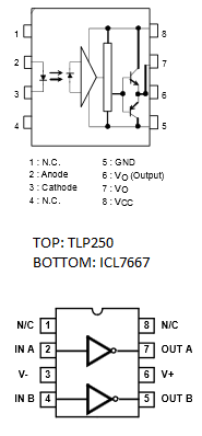
Go through the datasheets of the two devices. You'll see that you just can't substitute the ICL7667 for the TLP250.

Here's a diagram comparing just the pinouts:

6480836800_1387781176.png


You must keep in mind that they are not functionally the same either.

Hope this helps.
Tahmid.
 

Can you please help me to knwo how I can step up without transformer the output of H-bridge?
I used your technique available onhttps://tahmidmc.blogspot.com/2012/10/generation-of-sine-wave-using-spwm-in_10.html by generating an SPWM signal but I have a problem because when applying on the circuit the SPWM signal and 220VDC I get only 6VAC/50Hz at the output of H-bridge made by IRFP460Z.

is that right I thing with those components I might get more than that but I don't know why I am getting only 6VAC/50HZ;can you please help me to identify the problem?
For the ICL7667 I am using them for driving the MOSFET.

Thanks,please help.!!
 

For the ICL7667 I am using them for driving the MOSFET.
After all previous posts, the attitude can be only considered as resistant to advice.

Furthermore you never showed a clear schematic, so we just have to guess that your design is terribly wrong.
 

The last schematic I have seen from your side showed a H-bridge with IR2110 drivers, supplemented by the statement that you are actually using ICL7667. All discussions that ICL7667 can't work for H-bridge control apparently didn't leave a mark.
 

Hi Tahmid,
It is really really nice to see you to take a good care of this thread. :)
Maybe you should give correct mosfet driving circuit before some guys blown up more mosfet.
And also, please don't forget to make them some explanation of Vgs threshold level, linear and saturation region, ton toff prochedure, dv/dt, voltage transient, fast recovery diode, emc, and of course isolation method before someone get strike.
 

Status
Not open for further replies.

Part and Inventory Search

Welcome to EDABoard.com

Sponsor

Back
Top