Continue to Site

Welcome to EDAboard.com

Welcome to our site! EDAboard.com is an international Electronics Discussion Forum focused on EDA software, circuits, schematics, books, theory, papers, asic, pld, 8051, DSP, Network, RF, Analog Design, PCB, Service Manuals... and a whole lot more! To participate you need to register. Registration is free. Click here to register now.

Calculation of gate resistor wattage

Status
Not open for further replies.

deepakchikane

Full Member level 3
Joined
Jul 17, 2012
Messages
178
Helped
2
Reputation
4
Reaction score
2
Trophy points
1,298
Location
Mumbai, Maharashtra, India, India
Activity points
2,623
Dear all,

1) How to calculate the wattage required for gate resistors..??

2) How to calculate current required to the Mosfet from datasheet..??

Looking forward to hearing you soon..!!


for IRF 730 MOSFET..!!
 

Attachments

  • irf730.pdf
    197.2 KB · Views: 220

A gate doesnt takes any current but if you shunt it with some resistor for protection then you have to calculate the current by two resistors in series then you can calculate power of each resistor...

Typically you can use 1/4 watts.

The current rating is shown in table
"ABSOLUTE MAXIMUM RATINGS (TC= 25 °C, unless otherwise noted)

Continuous Drain Current VGSat 10 V TC= 25 °C ID 5.5A TC= 100 °C 3.5"

at 25°C it is 5.5A and at 100°C it is 3.5A.
 

@VENKATESH:
AGREE AT ALL...

there is need of current to charge the capacitors...

withot charging internal cap,hw it can powered up..
giving 10 volt directly-it will leads to cc limit..

dats y i am looking out to find the required current for the mosfet..

How u will be turn on the mosfet..??
plz check the mosfet features
 

It was going to be a very very low value look at the graph cap = Q/V
untitled.JPG
the gate cap is very low value, It will be in nA..
 

wot u want to elaborate

dat i am not getting..

simple thing,
i want to charge that capacitors with vgs 10v at certain current..

that certain current i am unable to calculating.. :(
 

Ok cool, for Vgs = 10V

the gate charge is 25nC(from the table)..

Current is moving of charge (coulombs per second)..

current is going to be how fast the capacitor charging or turning the mosfet ON.. after the capacitor charging the current will be zero...

It doesnt matter how much resistor you are putting in the gate it matters how much voltage is in the gate..

Really I don know how to explain...........


Thnxxx.. this is what i want where i was confusing between voltage & current.. :)
 

Calculation of gate resistor wattage

Dear all,

1) How to calculate the wattage required for gate resistors..??

2) How to calculate current required to the Mosfet from datasheet..??

Looking forward to hearing you soon..!!


for IRF 730 MOSFET..!!

Hi deepakchikan
It is simple .
You know about Tr of your mosfet . ( rise time ) ( by datasheet )
Vc=1/C integral over ic dt ====> from zero up to tr ====> Vc=tr*ic/c ===> ic = Vc*c/tr for usual mosfets VGS=15 it will be turned on . so Vc=15 then required ic = 15*ciss/tr and of course it is inrush current . so required power of the series resistor with gate can be calculated according to this inrush current .
Best Wishes
Goldsmith

Thnxx Goldsmith...

- - - Updated - - -

Dear Goldsmith,

1)The resulting ic will be the gate current of mosfet..??

n hw we can calculate the current requirred to mosfet fully on..??
i am goin on this formalA

I=TOTAL GATE CHARGE (Q)/Ton OF MOSFET..

(will Ton=Td(on)+Tr..??)

Is this a correct way.. ??

correct me if i am wrong in calculations..
 
Last edited:

Dear Goldsmith,

1)The resulting ic will be the gate current of mosfet..??
Hi deepakchikane
Yes it will be the required inrush current for gate of your mosfet so the mosfet being turned on as well as fast as possible .
correct me if i am wrong in calculations..
There are many ways for everything in electronics . electronics is very good because you won't have just one way !
The way that i've suggested is according to the main equation of a capacitor ic=c*dv/dt
I have saw many ways for calculating gate inrush current . it is up to you to go though which one . ;-)

Good Luck
Goldsmith
 
Last edited:
Hi deepakchikane
Yes it will be the required inrush current for gate of your mosfet so the mosfet being turned on as well as fast as possible .

There are many ways for everything in electronics . electronics is very good because you won't have just one way !
The way that i've suggested is according to the main equation of a capacitor ic=c*dv/dt
I have saw many ways for calculating gate inrush current . it is up to you to go though which one . ;-)

Good Luck
Goldsmith

Goldsmith..
Thnxxx.. I AM INSTANTLY GETTING MY ANSWERS FROM YOU..

HATS OFF FOR YOUR KNOWLEDGE..

yeah... definately i am confusing in electronics..

coz i dont have right directions coz i simultaneusly read 5-6 datasheets,application note & choose the easier one to read..
bt this is my born in fault.. :)

please give me right direction for power electronics books & analog circuit design..


*i love to play with the electronics.. coz electronics is my first girlfrend...when i decided to work for power electronics jobs...

thnxx again
 

please give me right direction for power electronics books & analog circuit design..
Hi again
Ok
For power electronics :
Switching power supply design by Abraham I pressman
Switch mode power supply cookbook by Marty brown .
Power electronics by muhammad rashid ( it is not so practical by for understanding some of the theories is good )
Power electronics by Ned Mohan

Fundamentals of micro electronics by Behzad Razavi
Micro electronics by Jacob Millman
Micro electronics by Adel sedra

*i love to play with the electronics.. coz electronics is my first girlfrend...when i decided to work for power electronics jobs...
It is your first but it is my only ! :wink:

Good Luck
Goldsmith
 
There's a much simpler way to do this...
1) Find total Qg for your given drive voltage Vgs
2) Total power dissipated in gate drive is Qg * fsw * Vgs.
3) That dissipation will be distributed between the gate resistor, the internal gate resistance of the FET, and the gate driver's own ESR.

This approach is valid assuming that Vgs is allowed to reach steady state after each switching transition (which should always be the case), for unipolar gate drive.
 
The only thing that i couldn't understand yet , is why humans should fight together ? why not helping each other to have a better world ?

Superb..

there is no word for this sentence.. if everyone stop pulling legs of everyone then world will be simpler..
hats off to u sir...!!
 

mtwieg - your equation is correct to discover what the AVERAGE current draw will be from your gate drive power supply, so that is the correct equation to help determine power supply sizing. it will not tell you what the peak current will be.

most definately your mosfet will have a peak current because the action is to charge an "effective" gate capacitance through a gate resistor. however, to determine peak current you can not use i=cdv/dt because this equation does not take the gate resistor into consideration which changes A LOT the peak current achieved. there are a few appnotes out there that describe this properly. i don't have the full equation off the top of my head but i recall i read it in Microsemi, Sensitron, infineon app notes and it was an eequaiton that based based on RC time constant and the shape of the charge current being triangular. this is verified in PSpice too by the way. the peak current is important because this value must be supported by your mosfet gate drive IC.
 
For the total gate charge of Qg=38 nC, if you want to charge it within 38 ns, you need to drive it (by gate drive circuit) with 1A of current.
 
most definately your mosfet will have a peak current because the action is to charge an "effective" gate capacitance through a gate resistor. however, to determine peak current you can not use i=cdv/dt because this equation does not take the gate resistor into consideration which changes A LOT the peak current achieved. there are a few appnotes out there that describe this properly. i don't have the full equation off the top of my head but i recall i read it in Microsemi, Sensitron, infineon app notes and it was an eequaiton that based based on RC time constant and the shape of the charge current being triangular. this is verified in PSpice too by the way. the peak current is important because this value must be supported by your mosfet gate drive IC.
Hi Mr cool

Did you see what i told in my other posts in this topic ?

Of course that formula can be used . because everywhere which we have a capacitor we are dealing with that equation too . the gate resistor can be considered in the equation too . if we expand that equation we'll have this :Vc(t) Vs-(vs-vinit)*e^-tr/RC ok ? hence Vinit can be considered as zero so Vs(1-e^-tr/RC) can serve the aim as well where VC=15volts . ok ? ( the equation can be simply derived from the differential equation of capacitor .

Best Wishes
Goldsmith
 

the original post was about calculating the wattage of teh gate resistor. if you use i=c*dv/dt you will get a theoretical peak current across 0 ohms .. so your wattage is 0 and no power dissipated (capacitor fully charged though so that's nice). if you then took this peak current and decided that I^2*Rgate = wattage, you would end up with a wattage rating that is higher than it needs to be.

this is why to consider the gate resistor in determining wattage. resistor value and its effect on the rise time of the charge current and then take the RMS of that waveform to determine the wattage. so the trick is to know the shape of the waveform in both charge & discharge and to see if the discharge current goes through the same resistor or maybe a different resistor so you can determine Ron watt and Roff watt rating.

now what happens when you are on the bench and you try different gate reesistor value during the tuning process. yikes.. that's not good.. caues the watt rating can change as you change resistor value. so maybe the worse case method would be preferrable during development after all, gives you lots of room to freely chose gate resistor value that is optimal :)
Hi Mr cool
I know exactly what was the purpose of this thread and what was the original question but i'm sure everybody which is familiar with circuit analysis theorem is simple able to calculate it with what i've suggested .
If you know value of the current you can simply take average from it .
Simplification : calculation of that wattage won't take time more than 1 minute !
I'm not saying about bench and trial and error or something like that here in this thread . what i'm suggesting will deliver a precise value . but i didn't know that you'll come and say something about P=R*I^2 to me . be sure if i knew i would discuss what i was suggesting more in order to prevent misunderstanding ;-)

Wish you the best
Goldsmith
 
Maximum rating of gate resistors can be exeeded in two regards:
- average power
- peak pulse power versus pulse duration

If you neglect gate driver output resistance and internal MOSFET gate resistance, average power only depends on gate voltage, gate capacitance and switching frequency and can be simply calculated as Pv = Vg²*Cg*f (assuming unipolar gate drive and constant Cg). Interestingly it's independent of gate resistance.

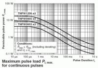
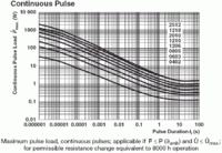
Pulse power is a more complicated thing. It's not always specified in datasheets and varies by a larger factor between resistor types. The below diagrams of a standard thin film chip and a pulse proof high power thick film resistor show a considerable difference in peak power for short pulses, which strongly matters for the 10 ns range gate charging time.


You should check how your application fits the resistor characteristics, but it's quite easy to exceed the rather low peak power of standard chip resistors. The safety margin of this specification isn't clear, but you should at least expect reduced lifetime when exceeding the peak power rating.
 
Status
Not open for further replies.

Similar threads

Part and Inventory Search

Welcome to EDABoard.com

Sponsor

Back
Top