Continue to Site

Welcome to EDAboard.com

Welcome to our site! EDAboard.com is an international Electronics Discussion Forum focused on EDA software, circuits, schematics, books, theory, papers, asic, pld, 8051, DSP, Network, RF, Analog Design, PCB, Service Manuals... and a whole lot more! To participate you need to register. Registration is free. Click here to register now.

Calculating reflection coefficient of a multi-layer structure using HFSS

Status
Not open for further replies.

cherne-he

Junior Member level 1
Joined
Oct 13, 2014
Messages
17
Helped
0
Reputation
0
Reaction score
0
Trophy points
1
Activity points
131
Hi everyone,
I want to simulate a model described in a paper. But my simulation result isn’t the same with that in the paper. I’m not sure how to enter the complex relative permittivity. The real part is 9.52, and the imaginary is 5.27. Is the setup right in figure1 attached? The air box include the multi-layer structure without air gap.
Thank you in advance!
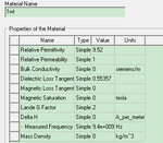
figure1.jpgfigure2.jpg
 

Imaginary permittivity is an alternative way to specify dielectric loss tangent. You should be able to derive the relation reviewing your text books.
 

Thank you for your reply! Could you write it more clearly? Thank you!
Imaginary permittivity is an alternative way to specify dielectric loss tangent. You should be able to derive the relation reviewing your text books.
 

Status
Not open for further replies.

Part and Inventory Search

Welcome to EDABoard.com

Sponsor

Back
Top