Continue to Site

Welcome to EDAboard.com

Welcome to our site! EDAboard.com is an international Electronics Discussion Forum focused on EDA software, circuits, schematics, books, theory, papers, asic, pld, 8051, DSP, Network, RF, Analog Design, PCB, Service Manuals... and a whole lot more! To participate you need to register. Registration is free. Click here to register now.

BRAM ROM Implementation in VHDL

Status
Not open for further replies.

Zerox100

Full Member level 6
Joined
Mar 1, 2003
Messages
328
Helped
21
Reputation
42
Reaction score
10
Trophy points
1,298
Activity points
2,604
Hi,

Is there any high level VHDL code that easily synthesized to a ROM in BRAM. I am working on a project and i need a 65536 single bit ROM in a Spartan-iii FPGA. I can use core generator, But i think it should be very good if i have a high level code that easily synthesized to ROM (a BRAM with initial value and write disabled) during synthesis process. Is it possible?
 

Where is the problem then :)
do what you are talking about !
generate the core using CoreGenerator, then instantiate it in your design and assign to the WEA (write enable of port A) in the port mapping a constant value '0' (this pin is active high). and don't forget when generating the code to specify the .coe file that will initialize the memory.

No i want high level coding style that ISE automatically synthesize it to a BRAM based ROM
 

sure, it is all in the manuals. see the XST user's guide. They have sections for inferring RAMs, ROMs, etc...
 

I have seen XST. But It does not have any useful information. I need a sample file. for example Could you explain a 16 bit ROM (16x1) with Initial Value "1100101010010111" in high level VHDL. It should be synthesize as BRAM not logic. Your kind attention to writing that sample would be appreciated.
 

you create a ROM by creating a constant that is an array of std_logic_vectors, and then access it synchronously.

Code:
type rom_array_t is array(0 to 2**n-1) of std_logic_vector(15 downto 0);
signal ROM : rom_array_t := (x"AAAA", x"5555" ..etc );  --you can also use a function to assign all values

--and then to access it
--use this first process if you want registered output data and async address
read_proc : process(clk)
begin
  if rising_edge(clk) then
    rom_output <= ROM(read_addr);
  end if;
end process;

--use this process if you want registered read address with async data - this is usually prefered method:
read_proc : process(clk)
begin
  if rising_edge(clk) then
    read_addr_r <= read_addr;
  end if;
end process;

rom_output <= ROM(read_addr_r);

--Of course, theres nothing wrong with registered the output data and the read address.
 

I have found cool code:


library IEEE;
use IEEE.STD_LOGIC_1164.ALL;
use IEEE.STD_LOGIC_ARITH.ALL;
use IEEE.STD_LOGIC_UNSIGNED.ALL;

entity bram8 is
port (
clk : in std_logic;
rst : in std_logic;
q : out std_logic_vector(7 downto 0));
end bram8;

architecture behavioral of bram8 is

signal addr : std_logic_vector(11 downto 0);

type init_array_type is array(natural range <>) of std_logic_vector(7
downto 0);

constant bram8_data : init_array_type :=(
X"00",X"01",X"02",X"03",X"04",X"05",X"06",X"07" ,
X"08",X"09",X"0A",X"0B",X"0C",X"0D",X"0E",X"0F" ,
X"00",X"01",X"02",X"03",X"04",X"05",X"06",X"07" ,
X"08",X"09",X"0A",X"0B",X"0C",X"0D",X"0E",X"0F" ,
X"00",X"01",X"02",X"03",X"04",X"05",X"06",X"07" ,
X"08",X"09",X"0A",X"0B",X"0C",X"0D",X"0E",X"0F" ,
X"00", X"FF"
);

begin

LUT_proc : process(clk)
begin
if( clk'event and clk='1') then
if(rst='1') then
q <= (others=>'0');
addr <= (others=>'0');
else
q <= bram8_data(CONV_INTEGER(addr));
addr <= addr + 1;
end if;
end if;
end process;

end behavioral;
 

I have seen XST. But It does not have any useful information. I need a sample file. for example Could you explain a 16 bit ROM (16x1) with Initial Value "1100101010010111" in high level VHDL. It should be synthesize as BRAM not logic. Your kind attention to writing that sample would be appreciated.

did you at least get to the table of contents before giving up? it has examples of RAMs/ROMs in both Verilog/VHDL. IIRC, it also provides a link to a zip file that contains example files of all the constructs in the xst guide, and more.
 
I have seen XST. But It does not have any useful information. I need a sample file. for example Could you explain a 16 bit ROM (16x1) with Initial Value "1100101010010111" in high level VHDL. It should be synthesize as BRAM not logic. Your kind attention to writing that sample would be appreciated.

If you want to do the quick-and-easy method then go with Malek Lamari's suggestion of using core generator. Block Memory Generator => Single Port ROM.

If you want to do the coding yourself, take a look at the "Libraries Guide for HDL Designs" for your chosen target, spartan-3. There are all the primitives with example code you need.

Sometimes I do a bit of both. If it's new for me, then I first do core generator. Then I take a look at the generated cores and the primitives in there, for inspiration on how to use those myself.
 
Help

Can someone help code me a 16bit ROM. (256*16 Rom) With the code similarly looking like this one:

This is an 8bit ROM. Please help. I've attached a PDF to guide you with the instruction sets for the 16bit ROM.
______________________________
library ieee;
use ieee.std_logic_1164.all;
use ieee.std_logic_arith.all;
use ieee.std_logic_unsigned.all;

entity ROM is
port( Clock : in std_logic;
Reset : in std_logic;
Enable : in std_logic;
Read : in std_logic;
Address : in std_logic_vector(4 downto 0);
Data_out: out std_logic_vector(7 downto 0)
);
end ROM;

--------------------------------------------------------------

architecture Behav of ROM is

type ROM_Array is array (0 to 31)
of std_logic_vector(7 downto 0);

constant Content: ROM_Array := (
0 => "00000001", -- Suppose ROM has
1 => "00000010", -- prestored value
2 => "00000011", -- like this table
3 => "00000100", --
4 => "00000101", --
5 => "00000110", --
6 => "00000111", --
7 => "00001000", --
8 => "00001001", --
9 => "00001010", --
10 => "00001011", --
11 => "00001100", --
12 => "00001101", --
13 => "00001110", --
14 => "00001111", --
OTHERS => "11111111" --
);

begin
process(Clock, Reset, Read, Address)
begin
if( Reset = '1' ) then
Data_out <= "ZZZZZZZZ";
elsif( Clock'event and Clock = '1' ) then
if Enable = '1' then
if( Read = '1' ) then
Data_out <= Content(conv_integer(Address));
else
Data_out <= "ZZZZZZZZ";
end if;
end if;
end if;
end process;
end Behav;
 

Attachments

  • Harvard Architecture Processor.pdf
    57 KB · Views: 165

Like I said before, you dont need a rom. YOu need a decoder that can action your instructions.
 

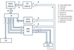
But our professor is making us a ROM. Here i'll attach the block diagram of our system so you'll understand what we're making. Also the PDF for the list of instruction sets needed to code for the ROM. They are needed to be translated to binary value.
 

Attachments

  • blockdiagram.jpg
    blockdiagram.jpg
    47.5 KB · Views: 97
  • Harvard Architecture Processor.pdf
    57 KB · Views: 142

The rom will just contain the program running on the CPU. I cannot tell you what to put in the rom because I dont know what the program is.
 

Status
Not open for further replies.

Similar threads

Part and Inventory Search

Welcome to EDABoard.com

Sponsor

Back
Top