slimbobaggins
Newbie level 6
Hi All,
While not technically RF frequency, the 1 MHz signal in question is my IF output of my RF system, and I thought I might have a bit better response posting this here, rather than in the analog section.
I'm mixing together 1497 MHz and 1496 MHz to get a 1 MHz output IF, filtering and amplifying, prior to transmission. I used the Raltron bandpass filter calculator, built it using close component values, and the filter response is actually really good.
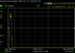
My problem is that as I get close to 0 dBm, my insertion loss starts to increase. I built the filter standalone and swept it with the NA, and took screen shots. You can see that as I increase power from -20 dBm to 3 dBm, my insertion loss increases by 0.1 dB, and continues to worsen as the power increases (for picture taking purposes, my NA power is limited to 3 dBm).
My question is... why? At 3 dBm, my inductors shouldn't be anywhere near their saturation threshold, and as a test, I wound my own inductors on toroids with cores from Amidon, which certainly should be below the saturation threshold, and still saw the same effect.
My output spec is +/- 0.1 dB, and I'm right on the threshold at 3 dBm, and above that I don't meet it. I'm stumped as to what I can do to fix this. I have done some google searching, but can't find an explanation online as to what the issue is. I've always been taught that passive filters have a very high P1dB and IIP3, so I don't understand why I'm having a problem at such a low power level.
Any suggestions?
Calculator:

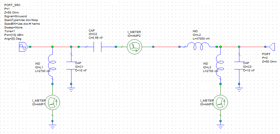
Schematic:

Increasing loss with input power:


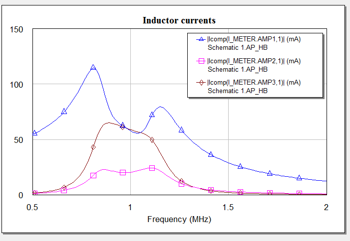
Expanded frequency response of filter:

While not technically RF frequency, the 1 MHz signal in question is my IF output of my RF system, and I thought I might have a bit better response posting this here, rather than in the analog section.
I'm mixing together 1497 MHz and 1496 MHz to get a 1 MHz output IF, filtering and amplifying, prior to transmission. I used the Raltron bandpass filter calculator, built it using close component values, and the filter response is actually really good.
My problem is that as I get close to 0 dBm, my insertion loss starts to increase. I built the filter standalone and swept it with the NA, and took screen shots. You can see that as I increase power from -20 dBm to 3 dBm, my insertion loss increases by 0.1 dB, and continues to worsen as the power increases (for picture taking purposes, my NA power is limited to 3 dBm).
My question is... why? At 3 dBm, my inductors shouldn't be anywhere near their saturation threshold, and as a test, I wound my own inductors on toroids with cores from Amidon, which certainly should be below the saturation threshold, and still saw the same effect.
My output spec is +/- 0.1 dB, and I'm right on the threshold at 3 dBm, and above that I don't meet it. I'm stumped as to what I can do to fix this. I have done some google searching, but can't find an explanation online as to what the issue is. I've always been taught that passive filters have a very high P1dB and IIP3, so I don't understand why I'm having a problem at such a low power level.
Any suggestions?
Calculator:
Schematic:
Increasing loss with input power:
Expanded frequency response of filter: