Continue to Site

Welcome to EDAboard.com

Welcome to our site! EDAboard.com is an international Electronics Discussion Forum focused on EDA software, circuits, schematics, books, theory, papers, asic, pld, 8051, DSP, Network, RF, Analog Design, PCB, Service Manuals... and a whole lot more! To participate you need to register. Registration is free. Click here to register now.

Binary weighted resistor ladder

Status
Not open for further replies.

storyee

Junior Member level 1
Joined
Apr 18, 2011
Messages
19
Helped
0
Reputation
0
Reaction score
0
Trophy points
1,281
Activity points
1,418
Hi there,

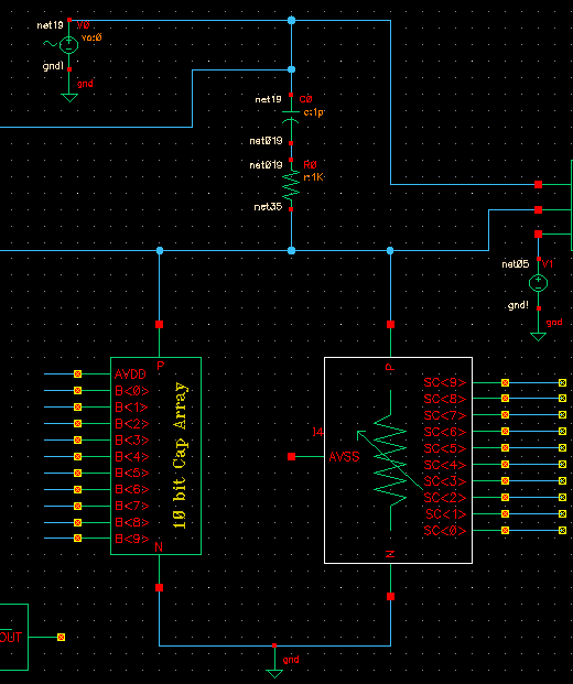
i am trying to design a 10-bit binary weighted resistor ladder, the ladder is switch controlled, and can get binary weighted values from R, 2R, 4R,..... 512R. And it can be sumed based on a SAR logic control. Is there such a ladder? I just want from two node, I can get different resistance which can be tuned based on a SAR logic. It look like a parallel connected switch controlled cap array.

Any ideas?

Thanks
 

The implementation would have to be an array of series resistors, each with a shorting device in parallel with it. The logic would be the inverse of the capacitor bank. For the parallel cap bank, you would close the switches to "add" a capacitor to the total. For the resistors, you initially short out all the resistors for R=0(Rmin), then remove the short-circuit across a single resistor to "add" it to the total series resistance.

You could do this is MOSFETs, but would need to carefully consider the biasing ON/OFF scheme. A simpler approach (albeit more power-hungry) would be to use multiple low-power signal relays to short the resistors. That would allow you to remove the concern for biasing each FET, since the switching side of the relay is electrically isolated from the control side.

Food for thought, you'll have to think through the FET idea to see if there are any major flaws in it, but that seems the most direct, and low-power alternative; albeit more complex to initially design.
 

Thank you so much for the suggestions,
However, I have considered the series connected scheme with switch to short different resistor to get linearly increased resistance along with digital codes. however, this scheme would mess up the resistance values since the turn on resistance of each MOS switch will parallel connected to the resistor and change the effective resistance values. I have to think another resistor ladder architecture to let me have the one like digitally controlled variable resistor. But I have not seen any schematics. So confused
Thanks anyway
 

If your values of R are large, and you use FETs with a really low Rds(on), then your impact should be minimized. What kind of resolution and range are you looking to achieve?
 

I need the min resistance around 10ohms, but also this resistor ladder will be used in high frequency application, the parasitic caps associate would be also problematic.
 

I need the min resistance around 10ohms, but also this resistor ladder will be used in high frequency application, the parasitic caps associate would be also problematic.

How high, is high frequency? Also, what are you trying to accomplish with this circuit? Perhaps there's a better overall solution to your problem.
 

Thanks,
let me show you part of the schematics, from the image, fixed R, C is unknown, based on algorithm, I need to tune 10 bit cap array and 10 bit Resistor array to find the unknown R C on top of the schematics, the circuit is excited by AC signal from 1MHz to 100MHz, in this case, I dont want parasitics affect results too much and also want the resistor ladder can generate digital controlled variable resistance values, and that resistance value should have enough accuracy


---------- Post added at 23:13 ---------- Previous post was at 23:00 ----------

How high, is high frequency? Also, what are you trying to accomplish with this circuit? Perhaps there's a better overall solution to your problem.

Thanks,
let me show you part of the schematics, from the image, fixed R, C is unknown, based on algorithm, I need to tune 10 bit cap array and 10 bit Resistor array to find the unknown R C on top of the schematics, the circuit is excited by AC signal from 1MHz to 100MHz, in this case, I dont want parasitics affect results too much and also want the resistor ladder can generate digital controlled variable resistance values, and that resistance value should have enough accuracy


Status
Not open for further replies.

Similar threads

Part and Inventory Search

Welcome to EDABoard.com

Sponsor

Back
Top