aht2000
Junior Member level 3
Hi,
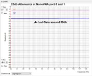
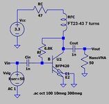
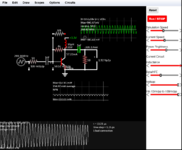
Sorry for the long post, but I am trying to verify my understanding with the experts on how the gain of the attached circuit (schematic attached) is calculated. I built the actual circuit on a PCB and measured its gain in the FM Band using a NanoVNA, and it shows 30db flat power gain (S21) taking into consideration the 20db attenuators installed on both ports of the nanoVNA (screen shot shows -10db).
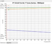
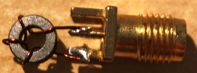
My understanding is the gain of the common emitter amplifier is Rc over Re (hope this holds true in the RF world too). In this case, I assume Rc is 47 ohm + impedance of RFC. I measured the S11 RFC alone using the NanoVNA (screen shot attached), and it is around 850 ohm of resistance. and 250 ohm of reactance ( |Z| = 900 ohm)
With Ic = 18mA, so Re = VT/18 = 1.3 ohm. I would expect the voltage gain to be (900+47)/1.3 = 728.
However as the output load is 50 ohm (port 1 of the nanoVNA), then I was expecting the above calculated gain to drop to 728* 50/(900+47) = 38.
Looking at the nanoVNA S21, it is 30db of power gain. if I calculate the same power gain based on the calculated voltage gain, it would be 20 log 38 = 31.6db with 1.6db deviation.
If I remove the RFC, then I assume that the RC is now only 47 ohm. So, the gain would be 47/1.3 = 36. As the output impedance is now 47 ohm almost equal to the 50 ohm load, so, I would expect the gain to drop by half to be 18.
And the power gain would be 20 log 18 = 25db.
So, the benefit of the RFC is that it gave me 5db more in power gain. Is this the case, or am I missing something? At the same time, it caused the output impedance and gain to be frequency dependent, and the output impedance became far higher than the typical target 50 ohm in RF.
I assume that the real benefit of the RFC comes when I am building a narrow band amplifier at which case I can build an LC matching network to match the amplifier output impedance to the 50 ohm load.
I sometime see in other schematics a capacitor connected from the point between the RFC and 47 ohm to ground. I assume that this is a bypass capacitor to prevent any RF who passed through the RFC to reach the power supply and its value should be chosen so that its impedance at the minimum frequency of interest at least 10 times less than the 47 ohm, and it does not cause a series resonance with the RFC anywhere in the amplifier band of interest.
Thank you.
Sorry for the long post, but I am trying to verify my understanding with the experts on how the gain of the attached circuit (schematic attached) is calculated. I built the actual circuit on a PCB and measured its gain in the FM Band using a NanoVNA, and it shows 30db flat power gain (S21) taking into consideration the 20db attenuators installed on both ports of the nanoVNA (screen shot shows -10db).
My understanding is the gain of the common emitter amplifier is Rc over Re (hope this holds true in the RF world too). In this case, I assume Rc is 47 ohm + impedance of RFC. I measured the S11 RFC alone using the NanoVNA (screen shot attached), and it is around 850 ohm of resistance. and 250 ohm of reactance ( |Z| = 900 ohm)
With Ic = 18mA, so Re = VT/18 = 1.3 ohm. I would expect the voltage gain to be (900+47)/1.3 = 728.
However as the output load is 50 ohm (port 1 of the nanoVNA), then I was expecting the above calculated gain to drop to 728* 50/(900+47) = 38.
Looking at the nanoVNA S21, it is 30db of power gain. if I calculate the same power gain based on the calculated voltage gain, it would be 20 log 38 = 31.6db with 1.6db deviation.
If I remove the RFC, then I assume that the RC is now only 47 ohm. So, the gain would be 47/1.3 = 36. As the output impedance is now 47 ohm almost equal to the 50 ohm load, so, I would expect the gain to drop by half to be 18.
And the power gain would be 20 log 18 = 25db.
So, the benefit of the RFC is that it gave me 5db more in power gain. Is this the case, or am I missing something? At the same time, it caused the output impedance and gain to be frequency dependent, and the output impedance became far higher than the typical target 50 ohm in RF.
I assume that the real benefit of the RFC comes when I am building a narrow band amplifier at which case I can build an LC matching network to match the amplifier output impedance to the 50 ohm load.
I sometime see in other schematics a capacitor connected from the point between the RFC and 47 ohm to ground. I assume that this is a bypass capacitor to prevent any RF who passed through the RFC to reach the power supply and its value should be chosen so that its impedance at the minimum frequency of interest at least 10 times less than the 47 ohm, and it does not cause a series resonance with the RFC anywhere in the amplifier band of interest.
Thank you.