Continue to Site
Follow along with the video below to see how to install our site as a web app on your home screen.
Note: This feature may not be available in some browsers.
if (RB0 == 0)
RB0 = 1;
else
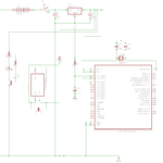
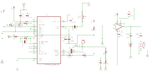
RB0 = 0;For the voltage on the IR diode you only need to calculate the proper R1 resistor:
Vm= main spupply voltage = 5V
Vd = Voltage on diode = 1.6V
Ad = current on diode = 50mA = 0.050A
R1 = (Vm - Vd)/Ad = (5 - 1.6)/0.050 = 68 Ohm
Yes, the problem of the IR sensor is because the PIC may drive components up to only a few mA, 25mA on most PICs. Your IR diode is rated 100mA so at half of that current should be given for it to work nicely. At 25mA it would merely start lighting. With a transistor you can increase the current as much as you need.
For series and parallel, i though you at least knew what they are and how to do it.. if not please search the elementary questions forum, I'm sure there is something about it.
Yes, putting the pin low or high means (respectively) GND or 0V, and 5V (TTL level) or 3.3V (MOS level). In your case, GND and 5V.