liletian
Full Member level 6
Hi Guys
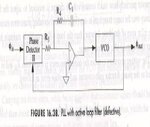
I found the attached PLL diagram. I am confused since there is no DC feedback for the amplifier which will definitely make the PLL misfunction. I only see R3,R4,C1 forms the necessary AC filter, however, without a DC feedback, it is not going to work. Can anyone help to explain the attached phase locked loop and also add the missing DC feedback of the amplifier in the graph?
Thanks
")