Continue to Site

Welcome to EDAboard.com

Welcome to our site! EDAboard.com is an international Electronics Discussion Forum focused on EDA software, circuits, schematics, books, theory, papers, asic, pld, 8051, DSP, Network, RF, Analog Design, PCB, Service Manuals... and a whole lot more! To participate you need to register. Registration is free. Click here to register now.

ADS1292R Communication

Status
Not open for further replies.

susane

Newbie level 6
Newbie level 6
Joined
Apr 12, 2016
Messages
14
Helped
0
Reputation
0
Reaction score
0
Trophy points
1
Activity points
128
Hello every one, i am an engineering student and i have been given a project, i want to communicate with ADS1292R with my Arduino UNO,
I have used the data sheet connections provided on page no 60.
i am using 4 wire SPI configuration, and for a good starting point, i just want to read a basic register with address 0x00, so i know that my communication is successful, but i am not able to do so,

Here is my code

Code:
#include <SPI.h>

int ADS1292_DRDY_PIN = 6; /// Not used for now
int ADS1292_CS_PIN = 10; ////// Working
int ADS1292_START_PIN = 5; /// Working
int ADS1292_PWDN_PIN = 4;////// Working
int ADS1292_CLK_SEL = 3; /// Working


int dat2 = 0;
int dat1= 0;


int RegData1 = 0;
int RegData2 = 0;
int RegData3 = 0;
int RegData4 = 0;
int RegData5 = 0;
int RegData6 = 0;


void setup() {
pinMode(ADS1292_DRDY_PIN, INPUT); //6
pinMode(ADS1292_CS_PIN, OUTPUT); //10
pinMode(ADS1292_START_PIN, OUTPUT); //5
pinMode(ADS1292_PWDN_PIN, OUTPUT); //4
pinMode(ADS1292_CLK_SEL, OUTPUT); //3


//////////// Power up sequence////////////
delay(10);
digitalWrite(ADS1292_PWDN_PIN, HIGH);
delay(9000);
digitalWrite(ADS1292_PWDN_PIN, LOW);
delay(100);
digitalWrite(ADS1292_PWDN_PIN, HIGH);
delay(1000);
////////////////////////////////////////////


///// Set CLKSEL to 1////////////

digitalWrite(ADS1292_CLK_SEL, LOW);
delay(100);
digitalWrite(ADS1292_CLK_SEL, HIGH);
delay(10);
//////////////////////////////////////////


/////// Setting start pin to LOW////////
digitalWrite(ADS1292_START_PIN, LOW);
delay(100);

SPI.begin();
SPI.beginTransaction(SPISettings(1000000,MSBFIRST,SPI_MODE1));

delay(1000); // Wait for SPI to begin

Serial.begin(9600);


}


void loop() {
// Sending the first command to ADS for SDAC so registers can be written

digitalWrite(ADS1292_CS_PIN, LOW);
delayMicroseconds(5);
SPI.transfer(0b00000010); //// SPI Command for Wakeup
delayMicroseconds(5);
SPI.transfer(0b00010001); //// SPI Command to STOP read data continous mode
delayMicroseconds(5);


SPI.transfer(0b00100000); // Read register command
delayMicroseconds(5);
SPI.transfer(0b00000000); // Number of Registers to read
delayMicroseconds(5);
RegData1 = SPI.transfer(0b00000000);// Dummy Data
delayMicroseconds(1);
RegData2 = SPI.transfer(0b00000000);// Dummy Data
delayMicroseconds(1);
RegData3 = SPI.transfer(0b00000000);// Dummy Data
delayMicroseconds(1);
RegData4 = SPI.transfer(0b00000000);// Dummy Data
delayMicroseconds(1);
RegData5 = SPI.transfer(0b00000000);// Dummy Data
delayMicroseconds(1);
RegData6 = SPI.transfer(0b00000000);// Dummy Data
delayMicroseconds(1);

digitalWrite(ADS1292_CS_PIN, HIGH);


Serial.print(RegData1,HEX);
Serial.print("\t");
Serial.print(RegData2,HEX);
Serial.print("\t");
Serial.print(RegData3,HEX);
Serial.print("\t");
Serial.print(RegData4,HEX);
Serial.print("\t");
Serial.print(RegData5,HEX);
Serial.print("\t");
Serial.print(RegData6,HEX);
Serial.print("\n");


}


If someone has experience with arduino and have done an SPI communication with this device, please help me
 

Hi,

i am using 4 wire SPI configuration, and for a good starting point, i just want to read a basic register with address 0x00, so i know that my communication is successful, but i am not able to do so,
* how do you know that communication is successful?
* What does this mean? "I´m not able to do so"

If the master starts an SPI communication, it will recieve data ... how do you know it does´t work?

Please give detailed error descriptions, otherwise it is impossible to help you.

Klaus
 

Sorry about my bad explanation,i am new to these forums,
the problem is that when i am reading register 0x00, all i am getting is a stream of "0" on the output.
and by successful communication i mean that when i will get the correct register value, i will be sure that my communication is successful.

All i need is a code for my arduino that can start the device and read the register 0x00 and print on serial monitor.
 

Hi,

Could you please post your schematic?

I´m going to your task.
all i am getting is a stream of "0" on the output.
This means the UART output?

***
You say you get "0". For us it is hard to see if "0" is a valid value or not. We need to go through the datasheet spending some time to find out what are valid values.
I assume you expect "0x73". Is this correct?

***
On first sight I can´t find out what´s wrong.

Do yo have a scope (2 channels at least)? Then show us the diagram of communication. Set trigger on falling edge of CSn.

Klaus
 

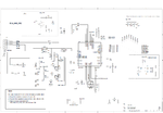
EDA_FORUM.png

This is the Circuit i am using.


***********
And i am using the ARDUINO framework so the output is displayed on the serial monitor of arduino framework

*************
And yes you are right i am expecting the value "0x73"
*******
Just a small update that i want to give to you is that, i just found out that my arduino was giving a 5v output and the ADS1292R is capable of reading signal within the range of 1.8 to 3.6
so now i have to use a logic converter or i have to modify my arduino to give a 3.6v clock.

But i dont know if that was causing the problem or what else.
But now i should add a level converter and then i will upload the pictures from a scope.

Thanks a lot for such quick and helpfull response from you klaus :)
i will update all the information soon on this thread and thn we can discuss more.
 

Hi

Arduino to ADC is 5V-->3.3V (Btw.: This may kill the ADC! Read datasheet.)
ABSOLUTE MAXIMUM digital input voltage is: DVSS – 0.3 to DVDD + 0.3 (in V)
A solution can be
* a current limiting resistor (I don´t recommend this)
* a two resistor voltage divider. (often a good solution. Especially because you already have the series resistor on your PCB)
* A 3V3 supplied gate with %V tolerant inputs
* A true 5V to 3V3 coltage converter IC.


But back: ADC to Arduino is 3V3 to 5V. What is the arduino´s valid high level? I expect about 0.7 x VCC = 0.7 x 5.0V = 3.5V.
The ADC high output level min. is 0.9 x DVDD = 0.9 x 3.3V = 3.0V

Often the interface form 3.3V to 5V works without problems. But it often is OFF specification.
I recommend to use a HCT buffer (mind the "T". It tells that it works on TTL input levels. High = 2.0V. So 3.0V is well within)

Good luck

Klaus
 
  • Like
Reactions: susane

    susane

    Points: 2
    Helpful Answer Positive Rating
Hi

Thanks a lot for the information, This was really helpfull :)
Now atleast i know what was wrong with my hardware, i will fix this issue and will be back here for more information.

Thanks Klaus :)
 

Status
Not open for further replies.

Similar threads

Part and Inventory Search

Welcome to EDABoard.com

Sponsor

Back
Top