Continue to Site

Welcome to EDAboard.com

Welcome to our site! EDAboard.com is an international Electronics Discussion Forum focused on EDA software, circuits, schematics, books, theory, papers, asic, pld, 8051, DSP, Network, RF, Analog Design, PCB, Service Manuals... and a whole lot more! To participate you need to register. Registration is free. Click here to register now.

Add LED to Tremolo guitar signal.

Status
Not open for further replies.

bzblues

Full Member level 1
Joined
Oct 11, 2020
Messages
99
Helped
0
Reputation
0
Reaction score
2
Trophy points
8
Activity points
822
Hi everyone! hope you are good!

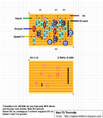
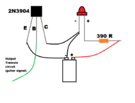
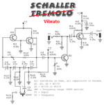
I have a question. I've built this tremolo effect guitar pedal and I was thinking ono addin and LED that reacts to the tremolo signal (blinking on and off). Now, the thing is that I linked the circuit to a guitar amplifier, so it's like a built in guitar amp with tremolo effect. I did my research on how to add an LED to a sound signal, by adding a 2N3904 transistor with a 390 ohm resistor to but In the end I would start blinking with or without the tremolo effect, just would react to the guitar signal, so the logical thing to do (at least for me) is to hook it up with the OUTPUT of the tremolo circuit. I tried that but nothing happened. I'll attach the Tremolo circuit and the LED circuit for you to see if I did something wrong.

Thanks in advance for the help!

Cheers!

Brian.
 

Attachments

  • Kay T1 Tremolo (2).png
    Kay T1 Tremolo (2).png
    50.9 KB · Views: 130
  • LED tremolo.png
    LED tremolo.png
    16.2 KB · Views: 159

First of all, a picture of a circuit board is useless.
Second of all, you've got the collecter and emitter shorted together. Why do you have have the LED connected to battery(-)?
Third of all, do you have a resistor in series with the base, or just a green wire?
 

Adding to Barry's comments... you also have to connect the negative side of the battery to the tremolo ground unless its the same battery that powers it already. Remove the wire between the battery '-' and the LED to start so the '-' side of the LED only goes to the transistor collector. You will probably still find it doesn't work though. The problem is that to make the transistor conduct you need about 0.6V on its base 'B' pin with respect to its emitter pin 'E' and there probably isn't enough voltage from the signal alone to reach that amount. You should also add a resistor is series with the base pin as Barry suggested, it protects the transistor and stops it distorting the signal it is driven from. I suggest 10K value.

Incidentally, the way you have it wired at the moment should make the LED light up all the time so if it isn't you have a wiring error or the LED is wired backwards.

Brian.
Hi Brian, thanks for the reply. I picked up the wiring from here: https://www.instructables.com/Creating-An-Audio-Reactive-LED-Circuit/

It all goes to the same battery that feeds all the circuits, the tremolo, the amp, and the added LED with the transistor. I figure what you said is correct about not beeing enough voltage to run the LED, althoug when I tested it, it light up just a little bit, but didn't react to the tremolo effect. Is not quite clear to me why the LED is wired backwards. I'll try and remove the wire that goes from the LED to the "-" of the battery and add the resistor to the Base of the transistor to see what happens.

Thank you!
--- Updated ---

First of all, a picture of a circuit board is useless.
Second of all, you've got the collecter and emitter shorted together. Why do you have have the LED connected to battery(-)?
Third of all, do you have a resistor in series with the base, or just a green wire?
Hi Barry.

Sorry about the pictures. I'm very new and I'm trying things and I still don't know quite well how to put this in schemantics.....

I picked up the wiringof the LED here: https://www.instructables.com/Creating-An-Audio-Reactive-LED-Circuit/

A 9V battery feeds all the circuits (the tremolo, the amp and the added LED) so I conected the LED to the part that feeds everything.
Don't quite understand why you say the collector and emiter are shorted out. In the link is showed like that and apparently it worked out.

The green wire is the output signal that comes from the tremolo circuit. That wire goes to the input of the amp, so I figured that there is where the LED should be added (the Base of the transistor)

Again, sorry if I'm not using the right terminology.

Thanks.
 
Last edited:

Sorry, but that's just a terrible design. First, they're shorting the two audio channels together. Second, there's no base resistor, as previously mentioned. Third, they don't mention that you're going to have to buy a new phone after you burn out the audio output. And, no, the link does NOT show collector and emitter shorted together.
 

I wasn't saying the LED was backwards but if it is wired as you show and it is the right way around it will light at full brightness all the time, regardless of any sound feeding it. If it s wired as shown and it isn't lit up, the LED is probably backwards.

I'm afraid you have fallen into the same trap many people do, believing what you see on the internet! I'm not being critical of you, there are so many dubious articles on the net that it can be tricky to find ones that either aren't completely fake or at least so inaccurate that they can't possibly meet the publishers claims.

The article you linked is connecting the transistor to the headset output of a phone where the voltage is relatively high, possibly several volts, that's how it makes the transistor 'turn on' and light the LED. In truth, if the LED was connected directly across the jack socket it would work equally well! The problem you face is the voltage at the point you have attached the transistor is probably a few millivolts, possibly hundreds of times smaller than used in the article. It doesn't mean its impossible to make it work but it does require some additional circuitry and complexity. Also consider that even if it did work, the LED would only flash in time with the sound, not the tremolo effect itself, it would make no difference whether the tremolo was changing the sound or not. If you want the effect itself to flash the LED you have to look at the difference between the input and output of the tremolo unit and amplify that enough to power the LED.

Brian.
 

I think the OP's intent is to connect his circuit to the output of the tremelo generator, not the final audio. (But I could be wrong). Regardless, without knowing what the input to this (dubious) circuit is, it's difficult to offer guidance.
 

Tremolo is a variation in the pitch (frequency) of the sound.
Vibrato is a variation of the volume (loudness) of the sound.
If your transistor driving the LED has a 22k resistor in series with its base then you must play fairly loudly for the LED to light and the transistor will cause some distortion in the sound.

I think the circuit is wrongly called tremolo, it is actually produces vibrato like this one:
 

Attachments

  • vibrato circuit.png
    vibrato circuit.png
    178.8 KB · Views: 98

Tremolo is a variation in the pitch (frequency) of the sound.
Vibrato is a variation of the volume (loudness) of the sound.
If your transistor driving the LED has a 22k resistor in series with its base then you must play fairly loudly for the LED to light and the transistor will cause some distortion in the sound.

I think the circuit is wrongly called tremolo, it is actually produces vibrato like this one:
Actually, it's the other way around. Vibrato is modulation of pitch; tremolo is modulation of amplitude.
 

There are conflicting definitions of Tremolo and Vibrato in Google.
Most dictionaries agree with me.
Fender Guitar Co says, "The Tremolo arm on a guitar actually produces Vibrato which is changes in the pitch".
Then why is it called a "Tremolo arm"??

The circuit that I showed made changes in the volume. I said it wrongly said Tremolo.
I think that singers use tremolo and vibrato at the same time.
 

Vibrato is pitch, tremolo is volume. Not sure what dictionaries you're using, but just ask any musician.
 

Status
Not open for further replies.

Similar threads

Part and Inventory Search

Welcome to EDABoard.com

Sponsor

Back
Top