Continue to Site

Welcome to EDAboard.com

Welcome to our site! EDAboard.com is an international Electronics Discussion Forum focused on EDA software, circuits, schematics, books, theory, papers, asic, pld, 8051, DSP, Network, RF, Analog Design, PCB, Service Manuals... and a whole lot more! To participate you need to register. Registration is free. Click here to register now.

actual output of sigma delta adc

Status
Not open for further replies.

sona_

Junior Member level 1
Joined
Nov 23, 2014
Messages
18
Helped
0
Reputation
0
Reaction score
0
Trophy points
1
Activity points
139
hello all

I have two queries on sigma delta ADC

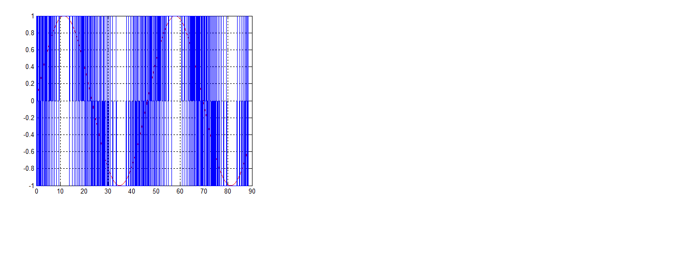
1. While going through its material i found that while some show that the output of the modulator is series of 0s and 1s, some show it as series of 1 and -1.
Which is correct

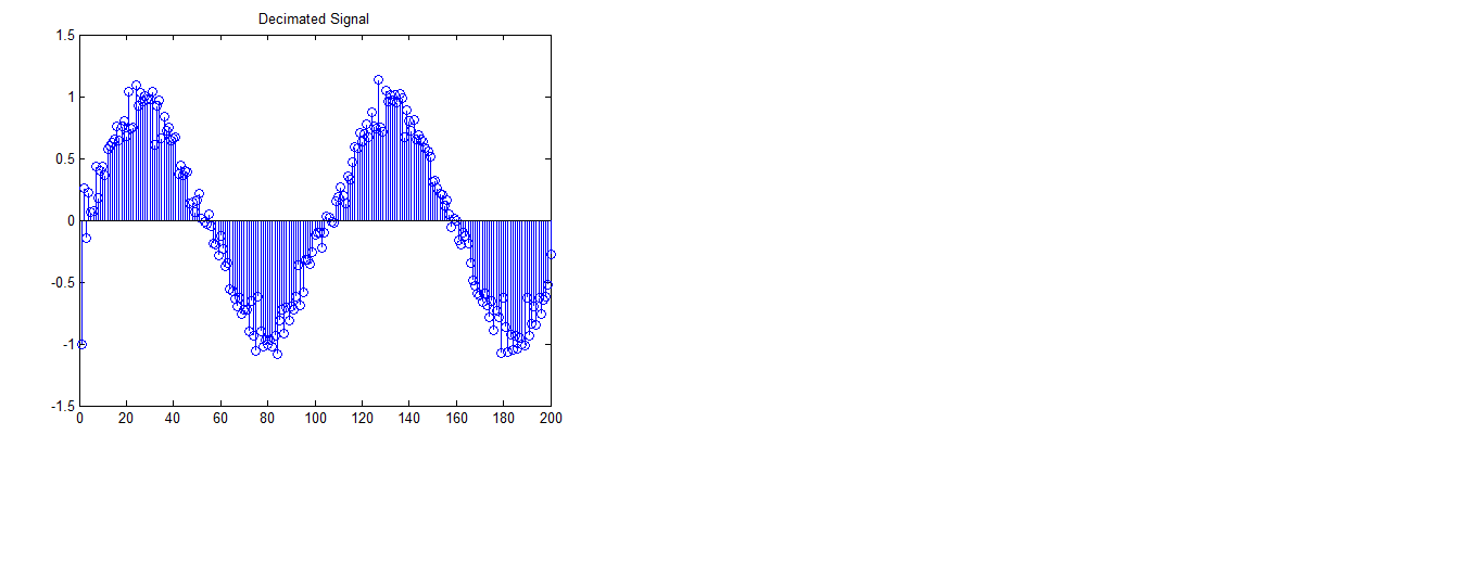
2. The output of decimator is shown as a discrete signal and not a digital (0 and 1). but the ADC should give a digital output.
https://www.ti.com/lit/an/slyt423/slyt423.pdf
AS I am new to this sigma delta adc kindly help. the more i look on the online avaliable material, more confused i get.
thanks in advance
 

1. The output is a binary digital signal, which is normally represented by 0s and 1s. The actual level depends upon the logic being used.

2. The output of the decimator is indeed a digital signal.
The digital filter and decimator converts the serial stream of 0s and 1s with coarse resolution from the sigma delta modulator into the series of digital word outputs representing the analog input, with the number of bits in each word determining the converter resolution.
This output is similar to the output from other types of A/D converters.
 
  • Like
Reactions: sona_

    sona_

    Points: 2
    Helpful Answer Positive Rating
1. The output is a binary digital signal, which is normally represented by 0s and 1s. The actual level depends upon the logic being used.

2. The output of the decimator is indeed a digital signal.
The digital filter and decimator converts the serial stream of 0s and 1s with coarse resolution from the sigma delta modulator into the series of digital word outputs representing the analog input, with the number of bits in each word determining the converter resolution.
This output is similar to the output from other types of A/D converters.

thanks a lot for your reply but could you please explain this to me.
1. kindly check the link https://blogs.mathworks.com/pick/2013/05/24/delta-sigma-toolbox/
this and many other show the output of modulator as series of 1 and -1 instead of 0s and 1s

2. pls see the link **broken link removed** by bonnie baker). this shows decimator output as discrete and not digital

kindly help
regards
 

1. They are showing it as +1 and -1 because they are using it to represent a sine-wave that goes plus and minus. The actual level is purely arbitrary as it's a digital signal. It could be +10 and -10 or 1 and 0, take your pick.

2. Your link doesn't work.
 
  • Like
Reactions: sona_

    sona_

    Points: 2
    Helpful Answer Positive Rating
1. They are showing it as +1 and -1 because they are using it to represent a sine-wave that goes plus and minus. The actual level is purely arbitrary as it's a digital signal. It could be +10 and -10 or 1 and 0, take your pick.

2. Your link doesn't work.

dear crutschow

loads of thanks for your reply.it was a great help indeed

1. i got the solution to problem 1
2. i am resending the link to problem 2 https://www.ti.com/lit/an/slyt423/slyt423.pdf
kindly check fig 1 block diagram

thanks in advance
 

Don't understand you comment about the decimator output of Fig 1 being "discrete" (?).
It's a digital output which is, by definition. discrete.
 

Is the SD-ADC output a discrete signal (time and amplitude discrete) or a digital signal?

It's actually both, as for any ADC. The ADC converts a time and amplitude continuous signal into a series of samples with quantized amplitude. In case of a 1-bit SD, the quantization has only two levels.

The discrete signal is represented a digital data stream, in case of the 1-bit SD a single bit stream. This digital electrical signal is time-continuous by nature, but holds information only at discrete time points.

hello
what is confusing me is the figure 1 block diagram of https://www.ti.com/lit/an/slyt423/slyt423.pdf
the output of digital filter. should it not be just the filtered output of previous section

thanks in advance
 

what is confusing me is the figure 1 block diagram of https://www.ti.com/lit/an/slyt423/slyt423.pdf
the output of digital filter. should it not be just the filtered output of previous section
Yes it should be.
The signal shown at the digital filter output, with some sort of amplitude modulation, does not make sense.
All the signals are in a zero and one type (binary) digital format.
Normally the digital filter and decimator are basically one unit, which serve to filter the high-sample-rate one-bit sigma-delta modulator signal and convert it to series of multi-bit words at a lower sample rate.
 

I see your point. The first filter stage is normally a decimation filter, so you won't see a multibit signal at the input sampling frequency fs. But theoretically, if you apply a low-pass filter with sampling rate fs, you could get a multibit signal.
 

I see your point. The first filter stage is normally a decimation filter, so you won't see a multibit signal at the input sampling frequency fs. But theoretically, if you apply a low-pass filter with sampling rate fs, you could get a multibit signal.
But the multibit signal would have a sample (word) rate lower than fs.
 

But the multibit signal would have a sample (word) rate lower than fs.
Not necessarily. A low-pass could average the SD bitstream without decimation. But as said, that's mostly theoretical and doesn't make much sense for a real design.
 

I see your point. The first filter stage is normally a decimation filter, so you won't see a multibit signal at the input sampling frequency fs. But theoretically, if you apply a low-pass filter with sampling rate fs, you could get a multibit signal.


hello all
the decimator output should not be as shown..but you know when i simulated output for 2nd order SD ADC the output of decimator actually comes out to like this only. things are write but do not understand why and how


thanks for ur replies all
 

Your input samplng rate is too low to get a good reproduction of the sine waveform, much superimposed quantization noise.
 

hello all
the decimator output should not be as shown..but you know when i simulated output for 2nd order SD ADC the output of decimator actually comes out to like this only. things are write but do not understand why and how


thanks for ur replies all
That right waveform appears to be
an analog (D/A) representation of a digital filter output of the left waveform.
 

That right waveform appears to be
an analog (D/A) representation of a digital filter output of the left waveform.
'

No, I have'nt used any D/A converter.
the Ist waveform to left is the ADC modulator output. then it is fed to the decimator. 2nd waveform (right) is decimator's output. i was thinking it to be wrong but this matches the decimator output of the link (fig 1) https://www.ti.com/lit/an/slyt423/slyt423.pdf. lots of confusion

please guide
I didn't mean to imply there was an actual D/A converter.
I'm just saying that the waveform "looks" like a D/A representation (for illustrative purposes only) of the filtered Sigma Delta signal.
 

I didn't mean to imply there was an actual D/A converter.
I'm just saying that the waveform "looks" like a D/A representation (for illustrative purposes only) of the filtered Sigma Delta signal.

ok..so what do you say..i guess the output is correct as can be compared by the link also(tutorial by bonnie baker).but i am not able to interpret it correctly
 

The output is as expectable.

My point in post #14 was that you see a considerable amount of quantization noise, if it's too much, you should adjust the sampling rate or the decimation filter bandwidth.
 

Status
Not open for further replies.

Similar threads

Part and Inventory Search

Welcome to EDABoard.com

Sponsor

Back
Top