Continue to Site

Welcome to EDAboard.com

Welcome to our site! EDAboard.com is an international Electronics Discussion Forum focused on EDA software, circuits, schematics, books, theory, papers, asic, pld, 8051, DSP, Network, RF, Analog Design, PCB, Service Manuals... and a whole lot more! To participate you need to register. Registration is free. Click here to register now.

AC coupling of a precision rectifier

Status
Not open for further replies.

Zaphappy

Junior Member level 2
Joined
Feb 28, 2011
Messages
21
Helped
1
Reputation
2
Reaction score
1
Trophy points
1,283
Location
Campbell, CA
Activity points
1,476
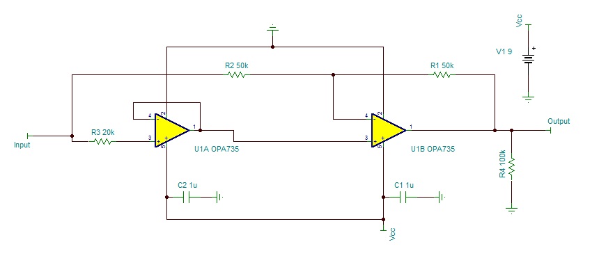
After much pulling of hair I realized my circuit didn't work because my signal generator was capacitor coupled.

I need the measurement to be AC coupled OR reject any DC that the signal may be riding on. How can I accomplish this ?


Add a non-inverting buffer amp (gain of +1) at the input to your precision rectifier circuit with a resistor to ground at the buffer input.
You can minimize part count by using a quad opamp for the three required amps.
 
I don't see a good way to save the circuit topology for AC coupled input, except for the rotten compromise of placing a low ohmic input resistor to ground.

"Zero drift" OPA745 is by the way no well suited for this kind of circuits due to it's extra overload recovery time.

A classical precision rectifier circuit with virtual ground at mid-supply would be my first approach.
 
Status
Not open for further replies.

Similar threads

Part and Inventory Search

Welcome to EDABoard.com

Sponsor

Back
Top