Continue to Site

Welcome to EDAboard.com

Welcome to our site! EDAboard.com is an international Electronics Discussion Forum focused on EDA software, circuits, schematics, books, theory, papers, asic, pld, 8051, DSP, Network, RF, Analog Design, PCB, Service Manuals... and a whole lot more! To participate you need to register. Registration is free. Click here to register now.

About the Conversion Gain of Mixers

Status
Not open for further replies.

shahriar22nd

Member level 2
Joined
Sep 24, 2009
Messages
45
Helped
0
Reputation
0
Reaction score
0
Trophy points
1,286
Location
Dhaka, Bangladesh
Activity points
1,663
Hello all,
I have a misgiving about the voltage conversion gain of mixers, That is defined as VIF/VRF, where VIF and VRF are the input and the output voltages of the (downconversion) mixer respectively. My question is- why this definition do not include VLO (the other input of the mixer)? Let me exemplify: in the ideal mixer attached herewith, VRF=V1.sin(2.pi.f.t), VLO=V2.sin(2.pi.f.t) and VIF=(V1.V2)/2 if the gains of both the mixer and the filter are 1.
87_1297256051.jpg

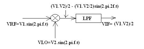
So, the conversion gain would be more palpable if CG= VIF/(V1.V2/2)=1 instead of VIF/V1=V2/2 i.e. if V1=V2=10mV, then CG=1 Vs .005. This seems perplexing to me.
Can anyone please tell me what am I missing here?
Thanks and Regards ...
 

Hi, shahriar22nd
Usually mixers operate in region where power of IF signal is constant on input LO power level. So we say conversion gain is 10 dB while LO power not less than -5 dBm. There is also usually upper limit for LO power.
 

The purpose of the LO is to switch the mixer. The mixer diodes are shorted in pairs causing the IF signal to be flipped in polarity at the rate of the LO signal. This alternating polarity applied to the IF (or RF) creates the up/ down conversion. Therefore the LO signal must be strong enough to fully drive the diodes, ideally the LO signal is a square wave of current. The amplitude of the LO is not important as long as it fully drives the diodes. If you simulate a signal to be flipped in polarity at some LO rate the spectral content of the output will show the how mixing works. The spectral content will show the desired signal and the other products, the desired signal will be 4-6dB down from the input.

The above is only true when the LO is strong enough to bias the diodes and the IF/RF is low enough to not affect the LO drive.
 

Thank you for your replies.
Dear Pavel_adameyko, I think you meant that, the LO power level remains constant while RF varies for giving rise to a variable IF output -you are right. But, still IF will depend on the LO power level, since it is changing the bias point of the mixing transistors (that will change the gain), given it is a large signal. By the way, so far I know, peoples usually use the LO power level that provided maximum gain while RF level was constant.
rfboardengineer is right as well, but only when LO is a large signal, as was mentioned there. But, to be specific, I am interested in multiplying two small sinusoidal signals of magnitudes 50mV each, say. Now the IF will considerably depend on LO, isn't it? Do I need to change the definition of gain for this particular case ?
 

For RF signal, 50mV is about -13dBm, that's not a small signal for receiver.
 

Thats right, 50mV is a large signal indeed :) , I overlooked it. Thanks for pointing it out. 50mV is -13dBm in a 50 ohm resistor if it is RMS voltage, but -16dBm if it is the magnitude level, that I mentioned there. Ok, let I need to multiply two 5mV sinusoids.
By the way, up to which power level do you call it 'small signal'? Microelectronic Circuits by Seda-Smith defines it as bellow 10mV in magnitude, not in terms of power level. Is there any definition based on power level?
 
Last edited:

LO signal has no effect on the Mixer operation but switching function.Therefore it's not included into gain definition because it's useless..
 

Hi there!

Yes you can mix the LO and RF with a conversion gain depending on LO

You just need to make LO small enough so that it doesnt operate in chop mode. I dont know the exact formulas anymore but for a gilbert cell mixer there is a multiplication of tangent hyperbolic functions with voltages refered to Vt, which is 26mV if I'm not mistaken. When your voltages are much lower than these levels, you will succesfully multiply LO and RF instead of just an upconversion/downconversion in chop mode.

Also note that conversion gain becomes meaning less in multiplication mode. But you can ofcourse define different gains for each spectrum line.. if your signals have fixed frequencies that is

Hope this helps!
 
Thank you, BigBoss for your reply. But, I'm interested in multiplying two small signals, that means, my LO is also a small signal, unlike frequency converters.

Hi Darkcrusher, you answered my question :)) . It matched exactly with what I anticipated. Thanks a lot for your clarification ....
 

Status
Not open for further replies.

Part and Inventory Search

Welcome to EDABoard.com

Sponsor

Back
Top