Continue to Site
Follow along with the video below to see how to install our site as a web app on your home screen.
Note: This feature may not be available in some browsers.
Your simulation package (Microcap) works fine and reliable.
Performing an AC analysis, no simulation package can discriminate between positive and negative feedback.
That is not a bug - it is rather the correct solution.
The reason is that during ac analyses, the simulator assumes that (a) the power supply is available since infinite negative times (no switch-on transient) and (b) that there is no disturbance of the equilibrium.
As a mechanical example: One small ball will ride upon a larger and will be stable if we assume that (a) that both are ideally centered and (b) that there is absolutely no external disturbance.
In the positive feedback example, the instability will be revealed only during transient simulation (time domain) when either the supply voltages or the input siganl are switched-on at t=0.
") Maybe I need to learn more about OPA principle...
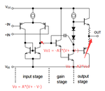
Maybe I need to learn more about OPA principle... Basically, the datasheet for all opamps shows the Large Signal Voltage Gain from an input to the output when there is no feedback. For the old LM324 it is typically 100,000 times. Positive feedback adds gain to the input and causes the opamp to amplify a very small input enough to cause the output to saturate as high or as low as it can go. Negative feedback subtracts gain, distortion and noise and can reduce the gain for the opamp to be useable. The ratio of the two negative feedback resistors determines the gain. Your second circuit has a gain of 10k/10k= 1 but since the input is to the (-) input, it inverts the signal.Maybe I need to learn more about OPA principle...
Basically, the datasheet for all opamps shows the Large Signal Voltage Gain from an input to the output when there is no feedback. For the old LM324 it is typically 100,000 times. Positive feedback adds gain to the input and causes the opamp to amplify a very small input enough to cause the output to saturate as high or as low as it can go. Negative feedback subtracts gain, distortion and noise and can reduce the gain for the opamp to be useable. The ratio of the two negative feedback resistors determines the gain. Your second circuit has a gain of 10k/10k= 1 but since the input is to the (-) input, it inverts the signal.
thx,,, I am just curious why that positive feedback OPA still working as negative feedback in MC11 simulator..
Audioguru - you have to discriminate between simulations in the time anf frequency domain !The simulator software that allows an opamp to work when it wrongly has positive feedback instead of correct negative feedback is stupid software.
Recall my mechanical example.
Under IDEAL condition (which, however, never can be realized in practice) an opamp with positive feedback would also be stable.
And for small-signal ac simulations the simulator assumes such IDEAL conditions. Remember: Before ac simulations (calculations) start the circuit will always be linearized around the corresponding DC bias point.
:-D thank you for the explanation.. Just try to use the idea opa to simulate the same circuit ,got the same result that it works on positive feedback,,, --- TINA 9 simulator.
:bang: it looks not so easy to understand
In this thread, who spoke about offset adjustments?It is impractical to set up an input DC voltage exactly the same as the input offset voltage and adjust it a tiny amount negative if the output begins to go positive and adjust the input voltage a tiny amount positive if the output begins going negative. If your adjustments are a little slow then the output will speed (snap action) to as high or as low as it can go and stay there.