Continue to Site

Welcome to EDAboard.com

Welcome to our site! EDAboard.com is an international Electronics Discussion Forum focused on EDA software, circuits, schematics, books, theory, papers, asic, pld, 8051, DSP, Network, RF, Analog Design, PCB, Service Manuals... and a whole lot more! To participate you need to register. Registration is free. Click here to register now.

About Injection Locked Oscillator

Status
Not open for further replies.

Kristya

Junior Member level 1
Joined
Sep 21, 2015
Messages
17
Helped
0
Reputation
0
Reaction score
0
Trophy points
1
Activity points
160
I need a 200MHz clock for TDC provided by ring VCO, but considering jitter accumulation conventional ring VCO doesn't fit. I want to design a injection locked ring oscillator, but can't find some proper paper. Can any one help me with some paper name?

Another question is how to simulate phase noise in this oscillator. When do PSS, the simulation stops because of the additional pulse injection,how to continue ?

Thank you for your help.
 

Time to Digit clocks (TDC) are measure in picoseconds. Using the tapped delay method, this is directly related to the linearity of delay and the temperature sensitivity of the delay elements. Phase noise is directly accumulates with variations in thresholds, signal slew rate and SNR.

I see a paper on TDC implemented on a XC4VSX35 FPGA with 50-60 picoseconds resolution, which may be of interest.

But the jitter spreads if there is no external reference and thus the Q of the feedback loop is a critical factor which is related to the overall time delay/deviation and number of delays. The f error between the SRF loop frequency and the harmonic number,n of the injected pulse if a lower f reference like 10MHz determines the capture range and phase noise is affected by Q, which in this case is determined by the non-linearity of each delay causing spread of delay times. Thus capture range and jitter are inverse as expected but dependent on amount of harmonic energy injected relative to the self generated energy, which is this noise in case or SNR.

That's all I remember from 35 yrs ago playing with ILL's.

Can't help with Sim fault, but injected pulse width must be on the order of magnitude of <1 tap delay.
 

I need a 200MHz clock for TDC provided by ring VCO, but considering jitter accumulation conventional ring VCO doesn't fit. I want to design a injection locked ring oscillator, but can't find some proper paper. Can any one help me with some paper name?

Another question is how to simulate phase noise in this oscillator. When do PSS, the simulation stops because of the additional pulse injection,how to continue ?

Thank you for your help.
Can you show a image or something like that? I know more detail about your idea
 

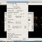
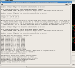
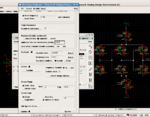
Following picture are the circuit I wanna test(simple enough), the PSS Pnoise simulation setting and the simulation error. 捕获1.PNG捕获2.PNG捕获3.PNG捕获4.PNG

I'm alone with this project and unfamiliar with this topic,can you show me where i was wrong and maybe some inscturctions of the circuit?

Thank you very much
 

Another question is how to simulate phase noise in this oscillator.
When do PSS, the simulation stops because of the additional pulse injection,
It is very natural result.
You are trying to do Autonomous PSS Analysis with driven signal V0 of 160MHz.
However it can never converge.

You have to do Driven PSS Analysis where fundamental frequency is 160MHz.
Here you have two options for PSS.
One is SN(Shooting-Newton).
The other is HB(Harmonic-Balance).

If it can not converge, try to do Autonomous Multitone Steady State Analysis such as Autonomous Multitone HB(Autonomous-QPSS).

Read my appends in the followings.
https://www.edaboard.com/threads/195061/
https://www.edaboard.com/threads/288049/
 

Status
Not open for further replies.

Part and Inventory Search

Welcome to EDABoard.com

Sponsor

Back
Top