Continue to Site

Welcome to EDAboard.com

Welcome to our site! EDAboard.com is an international Electronics Discussion Forum focused on EDA software, circuits, schematics, books, theory, papers, asic, pld, 8051, DSP, Network, RF, Analog Design, PCB, Service Manuals... and a whole lot more! To participate you need to register. Registration is free. Click here to register now.

A research neuroscientist needs your help making an isolated V to I converter

Status
Not open for further replies.

Bill.Connelly

Newbie level 4
Joined
Sep 30, 2011
Messages
6
Helped
0
Reputation
0
Reaction score
0
Trophy points
1,281
Activity points
1,333
Hi,

I need to build a device that converts the 0-10V output of the DAC port on my DAQ to a constant current source, in the range of 0-1mA. However, the output needs to be isolated from ground. Finally, the output needs to reach it's steady state level within about 20 microseconds. I am rubbish at electronic design (biologist). So I can not figure this out. I can see how to make an non isolated one, but not a non-isolated one.
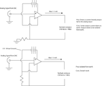
stimulus-isolator2.GIF

I purchased a commercial version at significant expensive, but it's temporal response was compeltely inadequate. But otherwise nice.
ds4.gif

Please, can someone help me. I really would appreciate hand holding on this, specific part numbers etc. The less time I spend figure out this (and blowing up poorly selected op-amps), the more time I can spend trying to cure epilepsy, and figure out how the brain transits from wakefulness to sleep. However, any help appreciated.

Edited image one to make what is required clearer
 

Attachments

  • stimulus-isolator.GIF
    stimulus-isolator.GIF
    12.3 KB · Views: 165
Last edited:

Linear Isolation can be done in so many ways but if you send clear inputs to me i can solve it . but any how i am providing the weblinks go through the links you can easily develop your own signal conditioning circuit.

weblinks

https://www.ti.com/lit/ds/symlink/iso120.pdf

**broken link removed**

I hope these two links are sufficient.
 

Ah, there is a problem. That variable resistance? We're talking on the range of 100k to 1MOhm... i.e. it needs to be able to deal with supply and output voltages of arond 100V... 50V would be okay.
 

Can You send full schematic with details where you really facing problem, i can solve it and i can reply on monday only . Not an issue problem can be easily solved. okay.
 

BTW: Actually, the bottom schematic of your first post (above) basically would work, it just doesn't provide a real isolation: the virtual ground somehow is connected to the amplifier's input GND (via the power supply).

Moreover -- depending on the value of your variable resistance -- there's not enough voltage headroom between the max. 10V input voltage and the +15V power supply of the output amplifier. It would be better to use a 10:1 voltage divider (90kΩ - 10kΩ) for the input, so the feedback resistor (1kΩ in this case) would "eat up" only 1V from the 15V power supply.

That variable resistance? We're talking on the range of 100k to 1MOhm... i.e. it needs to be able to deal with supply and output voltages of arond 100V... 50V would be okay.

1MΩ*1mA would need 1kV. In any case you'll need a -- from the input -- isolated power supply of that voltage you'll ultimately need for your variable resistance, and a (probably npn BJT) HV transistor, controlled by the output of the output opAmp, which can stand the HV, its collector to HV+, emitter to your variable resistance, HV- to the output amplifier's common terminal.
 

In specific answer to your question, this is an PM I just sent s.b.v.seshagiri:
I can describe exactly what I need, however, I have almost no idea how to design the circuit.

What I need:

A circuit that takes an input of 0 to +10V and "converts" it to an output of 0 to 1 mA (it would be perfect if it could take -10 to +10 V, and convert it to -1 to 1mA, but I can manage if it doesn't do that).

It will probably run of 11 9V PP3 batteries. And be driving a resistance of about 100kOhm to 1 MOhm.

This input needs to have a input impedance higher than about 10kOhm.

The output needs to be isolated from ground. That is, if I connect the positive terminal of the output to the ground, and trigger the device, no current will flow to ground.

The bandwidth of the output needs to be on the order of 20kHz, i.e. a square wave input should produce an output that has pretty much reached steady state in 10 microseconds.

The output should never oscillate

Finally, the output needs to be low noise. About a microamp of noise would be the most that could be used. Hopefully less.
I in my perfect system, I would imagine that if the command signal told the componentry to "try" to drive more current that the supply voltage could handle, it woult would simply max out.
 

Actually, the bottom schematic of your first post (above) basically would work, it just doesn't provide a real isolation: the virtual ground somehow is connected to the amplifier's input GND (via the power supply).
I was just up to post an answer, that the circuit basically does not work. Because the input refers to a singular ground node, that is unrelated to the floating power supply.

More generally, a specification for the isolation requirements is missing. If you say, it shall have optical isolation, it's O.K. of course. You should correct the schematic accordingly.

I have also a problem with ouput voltage & current specification, because 3 mA @ 1 Mohm refers to 3 kV rather than 100 V. When you decide to supply only 100 V, it's absurd to write min 100 kohm and max 3 mA. This should be clarified.

Even a low voltage of 100 V doesn't work with regular OPs.

As another point, it may be important to specify the maximum offset current. Particularly when implementing analog opto isolation, you'll have difficulties to reproduce zero output current. A similar problem arises with your noise specification. If pulse operation is intended, it may be helpful to define a maximum pulse width and minimal signal amplitude and squelch the output in idle state.

Bipolar operation needs a doubled supply voltage.
 

Yes, I understand Ohms law enough to know that you can't drive 3 mA over 1 MOhm with 100 V. The numbers are rough estimates. Because this is biology. One day the electrode will have a resistance of 100 kOhms, and five minutes later it will be 150 kOhm. The next day it may be 900 kOhm. If the resistance goes up, I will know my maximum current will go down. The Voltage of 100V, (or more likely 98) will be delivered by batteries (10x PP3), which also means this voltage will vary over time as the internal resistance of the cells increase.

For Bipolar function, I either limit myself to +/- 50 V, or get twice as many batteries. I get this stuff. What I don't get is what kind of circuit to build. I thought if I gave order of magnitude estimates, that would help you guys.
 

I know this isn't right either... but maybe it might give you guys something to point at and say "you need a resistor here" or... "The op amp A2 should have gets its inverting input from after the MOSFET"...
stimulus-isolator3.GIF
 

The red graph shows a response you would get if there is stray capacitance at your scope/cables.

Say your output load is 1 M ohm. (Your stated max load is about that.) It only takes 84 pF to cause the 84 uS time constant as labelled in the graph. Unknown stray capacitance can cause this.

Did the commercial unit claim suitable specs?

Did you try hooking up the commercial unit to the next stage of your project, with nothing else connected but the next stage of your project? The commercial unit may work satisfactorily after all.

Your specs are for 20 uSec to final level. This is one 50,000th of a second.

Say your load is 100K (your lowest stated figure), then your stray capacitance must not exceed 40 pF, in order for output level to rise quickly enough for your spec. (I'm using the conventional 5 time constants to reach final level.)

Additionally you must factor in propagation delays through several transistors in an op amp.

Then add the settling time (even if miniscule) required for the op amp to convert V to A using a feedback loop on the op amp.

You state a requirement for an isolated ground. I can't say how that will increase (or decrease) time delays.

In other words, to figure out how to meet such a tight time spec will take some thought and some experimenting.

Hope this helped.
 

The numbers are rough estimates. Because this is biology.
It's no problem that you don't know the exact operation conditions of your circuit. But making estimates doesn't save you from specifying what you want to build. It's O.K. to say 100k to 1M load and you decide to apply 100V maximum.

Referring to the sketched circuit from post #10, the problem is still the missing voltage reference. You can't have a an isolated battery on the right and a single wire connecting both circuits. The supply voltages have to be linked and the input reference (=ground) must be shared with the foot point of the current sense resistor, otherwise the circuit doesn't work. In other words, it can't provide isolation.

It's possible - in principle - to make a (non-isolated) differential current source with high common mode resistance, but most likely the common mode error current won't be acceptable for your application. At least, it has to be specified and checked against feasible parameters of a respective circuit.

Another drawback of the non-isolated differential source is, that it must provide additional supply voltage margin to keep the common mode resistance under all conditions. I guess, that a non-isolated output would be preferably designed symmetrically.

I previously assumed a true isolated design using analog opto-couplers or similar means. But it has limited DC accuracy, as said.
 

BradTheRad: No, it wasn't caused by stray capacitence. When I showed the results to the makers of the component I bought, they said "yeah, that's right"

The total capacitence of the system (once it comes out of the component) will be between 5 and 10 pF

It's O.K. to say 100k to 1M load and you decide to apply 100V maximum
Okay, that is what I am saying. But the circuit should be rated to deal with 1mA...

FvM, I largely understand what you are saying (though I never have grasped what 'common mode' means). So what have I done wrong.... where do the ground(s) need to be?
 

Status
Not open for further replies.

Part and Inventory Search

Welcome to EDABoard.com

Sponsor

Back
Top