Continue to Site

Welcome to EDAboard.com

Welcome to our site! EDAboard.com is an international Electronics Discussion Forum focused on EDA software, circuits, schematics, books, theory, papers, asic, pld, 8051, DSP, Network, RF, Analog Design, PCB, Service Manuals... and a whole lot more! To participate you need to register. Registration is free. Click here to register now.

555 circuit not working

Status
Not open for further replies.

avdrummerboy

Member level 2
Joined
Nov 10, 2006
Messages
49
Helped
1
Reputation
2
Reaction score
0
Trophy points
1,286
Activity points
1,622
flashing 555

Hey all, it's been a while.

I am building a project that needs a 555 timer IC to flash an LED, however I cannon get the LED to flash for the life of me.

I plug into the breadboard the 555 IC, the two resistors, the cap and hook up all the connections and quadruple check all connections however when power is applied, the LED turns on and stays on, sometimes fading off slowly. Any ideas why this simple circuit is not working for me?

Thanks in advance for any help.
 

555 circuit 50%

please upload the circuit, so we can analyze
 

working of 555 ic

can somebody explain to me how 555timer's ic works?
 

555 circuit

It is possible that the oscillating frequency is so high that you cannot follow the flashing.
Multiply by 100 the value of the capacitor to see any difference.
And please upload the circuit, otherwise nobody can help you.

Mandi
 

led flasher 555 circuit

4_1239481219.gif


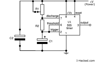
A basic astable mode circuit. R1 is a 500k pot (100k pot will work as well), R2 is 100k, and C1 is 0.47uF and C2 is .01uF.

Wanting about 10-14 flashes per second, and as I said, I hookup, triple and quadruple check all connections and no joy.
 

+555 +circuit

In addition to what you already have there, connect 10nF between pin 5 and GND - AND TRY ANOTHER 555 chip :!: ..

Rgds,
IanP
 

how to check if the ic of 555 is workinf or not

Hi, take care with your circuit. If you short-circuit R1 (zero Ω) it will be damaged due to excessive current at pin 7, since it connects it directly to VCC. Place a small resistor in series with your pot to avoid this. May be its already damaged.
 

fading circuit 555

Well I'm a total fool (runs and hides in shame :doh: )

I read the pinout wrong. Working fine now.
 

A quick question for those who know more than me, why does the LED flash brightly for some time then start dimming? Is it my component values. R1 and R2 both 100k, and C1 0.47 uF.
 

How are you connecting the led? How much current is flowing into it?
 

Battery was crapping out. Didn't think of that until later on.
 

Status
Not open for further replies.

Part and Inventory Search

Welcome to EDABoard.com

Sponsor

Back
Top