Continue to Site

Welcome to EDAboard.com

Welcome to our site! EDAboard.com is an international Electronics Discussion Forum focused on EDA software, circuits, schematics, books, theory, papers, asic, pld, 8051, DSP, Network, RF, Analog Design, PCB, Service Manuals... and a whole lot more! To participate you need to register. Registration is free. Click here to register now.

50 Ohm CPW best dimensions (ADS momentum)

Status
Not open for further replies.

alice12

Newbie level 4
Joined
Apr 28, 2016
Messages
7
Helped
0
Reputation
0
Reaction score
0
Trophy points
1
Activity points
65
Hello

I am trying to find the best dimensions for a CPW line by momentum simulations in the frequency bandwidth [1,400] MHz.

I did some simulations, I found a |S11| around -50dB for these dimensions:
- W=3 mm, G=0.5 mm and ground plane 6 mm.
But this is the case of a 10cm line.
When I increase the length to 40cm, a peak appears at 250 MHz and it reaches -10dB.
I don't know if this is normal ! Or a simulation error that I did.

Can you help me?

Otherwise, please, have somebody an idea for the best dimensions to choose (for a finite ground planes CPW) to get a perfect 50Ohm line in my bandwidth ?

Thank you a lot !! :)

Alice.
 

hi,
ads have a application/menu called linecalc. you can calculation dimension of whatever transmission line you want using linecalc. this is including CPW, microstrip, stripline and etc. try that and let me know if its works for you. based on my experience, whatever dimension i calculate using linecalc will be perfect 50ohm in simulation.
 
There is no such "best" dimension, there is only "right" dimension for CPWG.
These dimensions are absolutely depended on Substrate Parameters ( Er,Substrate Thickness,Dissipation Factor etc.). The length is a function of frequency if the Characteristic Impedance of the Line is different than System's Characteristic Impedance.
 
Hello,

I thank you for your replies !
Yes I used line calc in the begining (where I introduced all line/subtrate parameters) but I got a reflexion coefficient module around -20dB in Momentum simulations which is not enough for me.
So now I am optimizing these dimensions to get a better (lower) |S11|.
But, this peak that is bothering me.

Thanks.
Alice
 

what is the S11 you looking for? -20dB is good enough in my opinion.
 

Hi

I am working in (relatively) low frequencies, between 10 and 300 MHz, and in this band, having -20 dB isn't enough to have exactly 50 Ohm as Zc. When I represented Zc, I get 57 Ohm.

Please, is there so who have already simulated a CPW line on ADS and obtained exactly 50 Ohm when characterising it.

Thank you !
Alice

As others of stated, -20 dB for Return Loss is excellent impedance match. Typically requirements for sensitive impedance applications is -15 dB or better. -20 dB is only 10 % mismatch. I would start with a simple 2D field solver to understand what geometries are required to meet your 50 ohm impedance as a starting point.
 

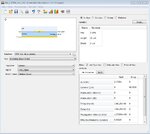
For better accuracy use Controlled Line Impedance Calculator in ADS

CILD.jpg
 

Status
Not open for further replies.

Part and Inventory Search

Welcome to EDABoard.com

Sponsor

Back
Top